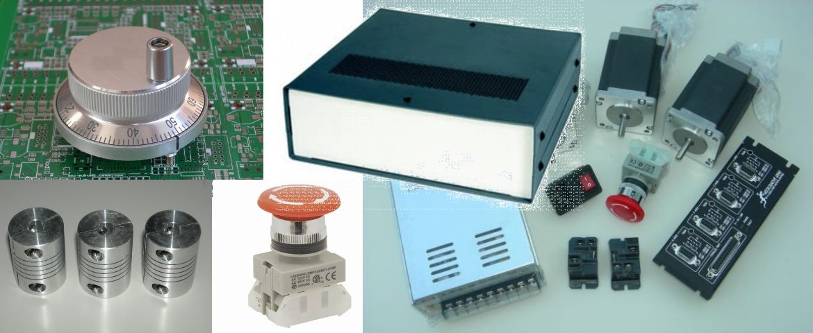
The Taig CNC mill with the Microproto MicroMill 2000HD controller is a combination that a lot of Taig users started off with. The Microproto controller is a 1/2 microstep Unipolar stepper motor driver. A good and robust controller in it's day, but in the end the driver gave out. I had repaired the Controller a number of times, but when the Geckodrive G540 was released, converting the mill over to the G540 was self-evident as the G540 is a complete 4 axis 10 micostepping drive system.
An impediment to using the G540 with the existing motors is that the Taig uses six wire Unipolar motors with a 6-pin din connector on the end of the lead, whereas the G540 is a bipolar stepper motor driver and needs the stepper leads to have a DB-9 connector on them. This problem is solved by constructing the adapter leads as described below.

The difference between the Taig Unipolar motors (a) and the bipolar motors (b) that the G540 is designed for is shown below. As can be seen below, the Unipolar motors have a centre tap in each of the two coils. The Unipolar motor can be treated as a Bipolar motor by using the centre tap and either one of the coil ends. You could also use both ends of the coil and ignore the centre tap but as the Geckodrive prefers low inductance motor coils, using the centre tap is the preferred option.

The Taig MPS Controller uses 6 pin DIN connectors for it's motor wiring. The stepper motors are wired as below;

Rather than cut the existing DIN plug off the stepper leads, I decided to make an adapter lead between the existing DIN plug on the Stepper motor lead and the DB-9 connector that will plug into the Geckodrive G540. The parts needed for each adapter lead is a;
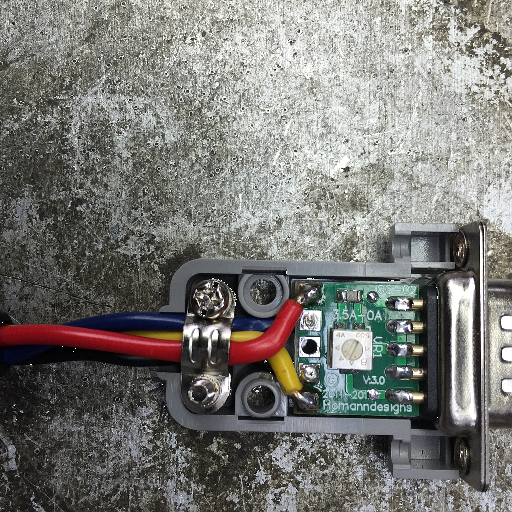
- GC-02 DB-9 Breakout board
- 6 pin DIN female inline socket
- Four short 18AWG wires.

The Adapter lead wiring need to wire the Unipolar coils to the Bipolar drive as depicted below. As can be seen, the G540 'A' Coil is connected to the stepper half coil leads 4 and COM24. The 'B' Coil is connected to the stepper half coil leads 1 and COM13. Note that the half coils 2- COM23 and 3-COM13 are not used. It is important to wire up each of the adapter leads identically so that they are interchangeable and that the stepper rotation direction for all steppers is the same.
To make the job easier I used a set of GC-02 breakout boards. They make soldering to the DB-9 a lot easier and have a trim-pot to set the current for the stepper motor. The stepper motors provided with my Taig CNC mill are rated at 1.4A so I set the trim-pot resistance to 1.4Kohm.

The first thing I did was remove the unused pins from the socket by cutting the solder tags off. They then fall out of the front of the connector. Removing the pins declutters the back of the connector making the job a bit easier.

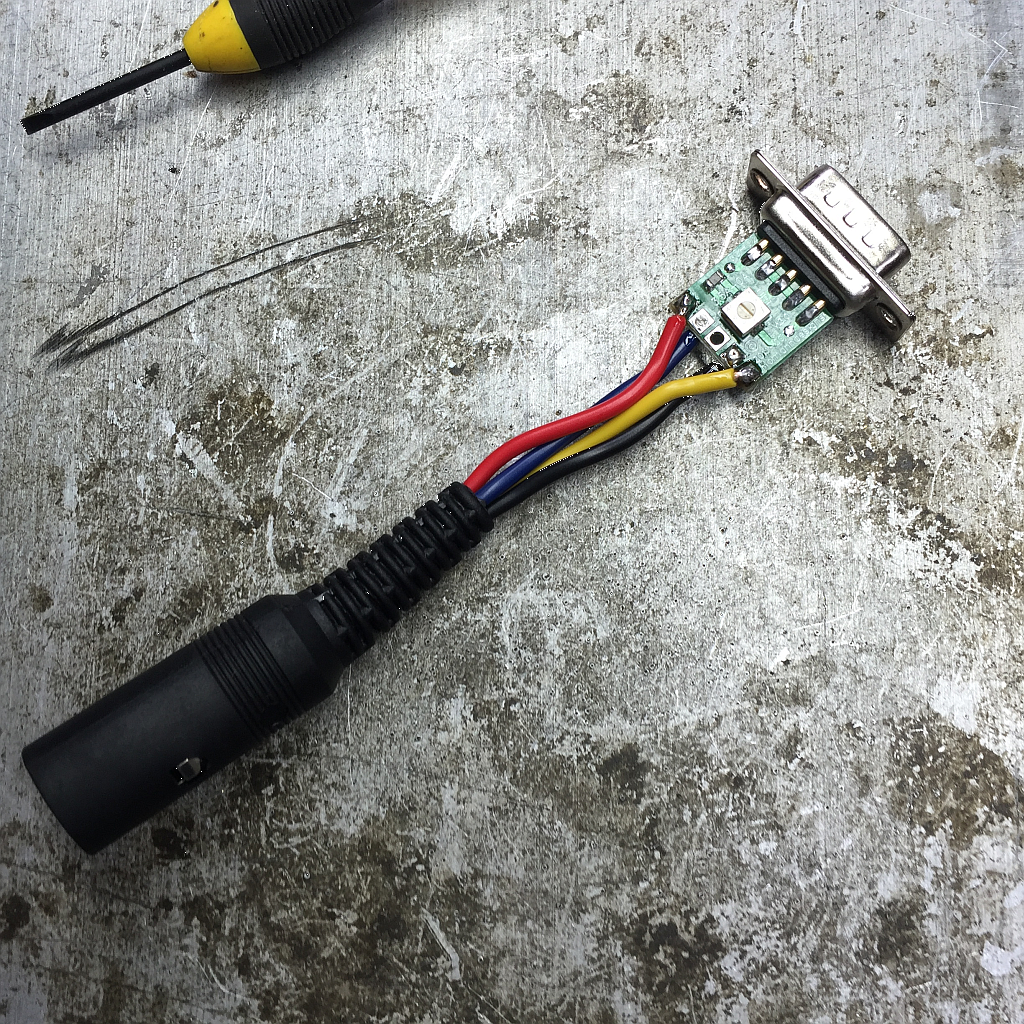
The four wires were then soldered to the DIN connector. As it is quite cramped inside the connector, it is important to put heatshrink tubing over the soldered joints.

The DIN connector was then reassembled. Time to do the other end.

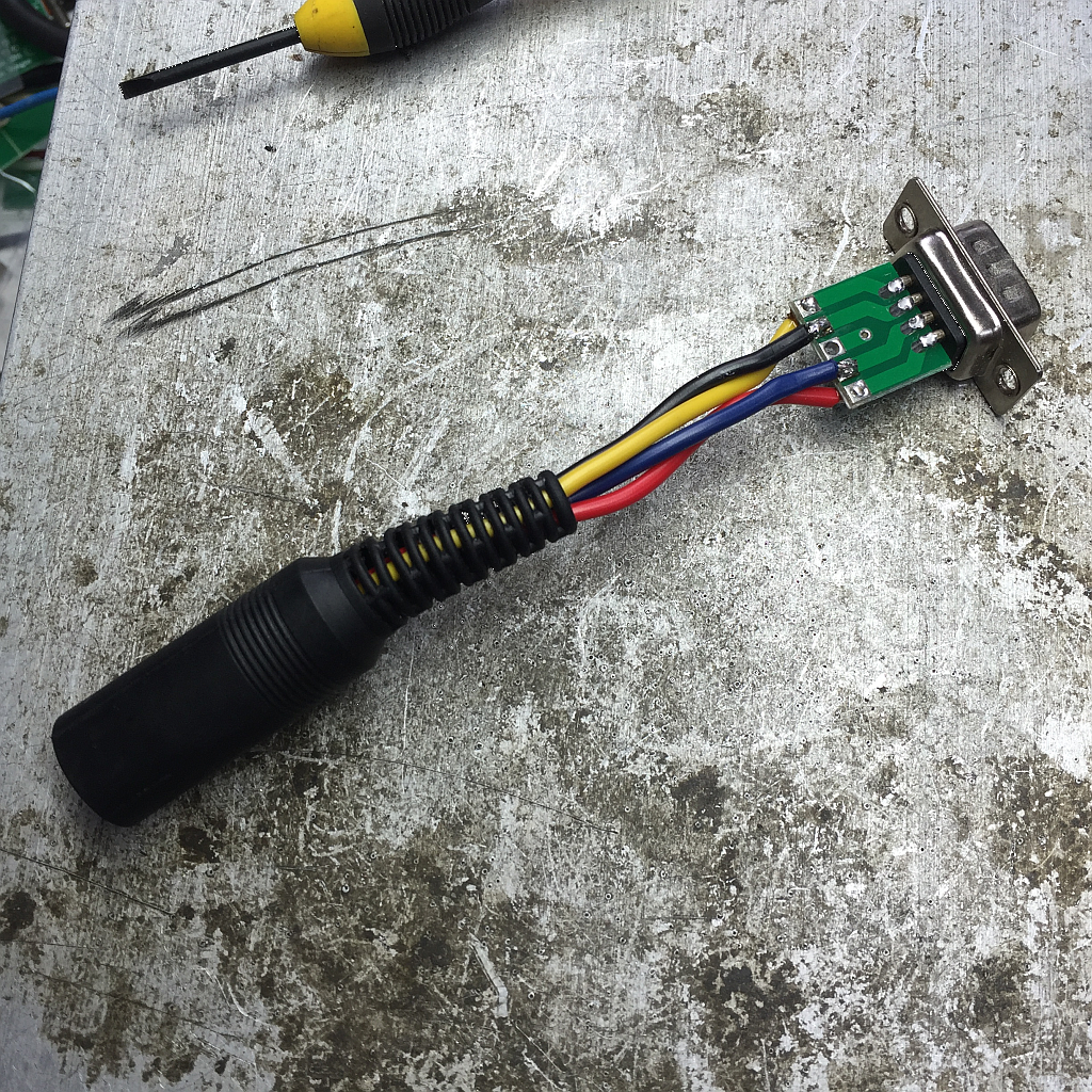
The Panavise makes holding parts for soldering a breeze. The four leads need to be soldered to the GC-02 breakout board.

The diagrams below show how I solder up the GC-02 breakout boards. As can be seen, it is quite a tight fit inside the backshell, so care and planning is needed.
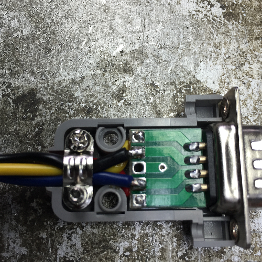
All that is left is to do the other three, test them and put them to good use.