I managed to start the Z-axis conversion over the weekend.
The new nut holder is to be made in two parts. This is so that it can be assembled into the column. The larger size of the RM2005 ballnut in comparison to the original nut makes it impractical to make the nut holder in piece.
The ballnut holder is made in 2 parts as shown below for easy assembly into the column. The plan is to;
- mount the lower cube part onto the ballscrew nut
- then insert the ballscrew into the column
- Attach part 2nd part of the nut holder to the first
- Mount the nut holder to the Z-Axis slide
The two parts need to lock together so I decided to make a square peg that locks into a matching square pocket.
The first job was to make the square peg. The part is made out of 50mm x 25mm aluminium stock. The peg dimensions are 25mmx 20mm.
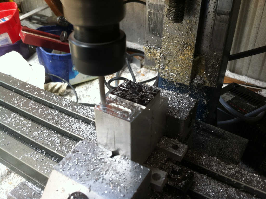
The material (15mm) either side of the peg was removed on my Taig mill. and the peg was then reduced so it was 12mm tall.
Two clearance holes for the 6mm capscrew mounting bolts were drilled.
The part was then flipped over and the holes were counter sunk for the mounting bolts.

As depicted in the images below part A of the Z-axis ballnut contains a pocket for part B to lock into. The two parts are held together with a pair of M6 bolts.
Part A is attached to the ballnut with 4 x M6 bolts. The block is 50mm x 50mm so two of the 6 mounting holes are not used.
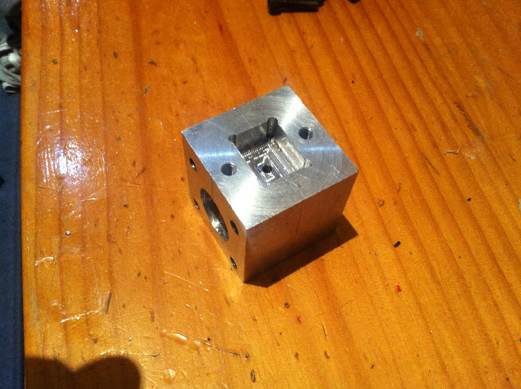
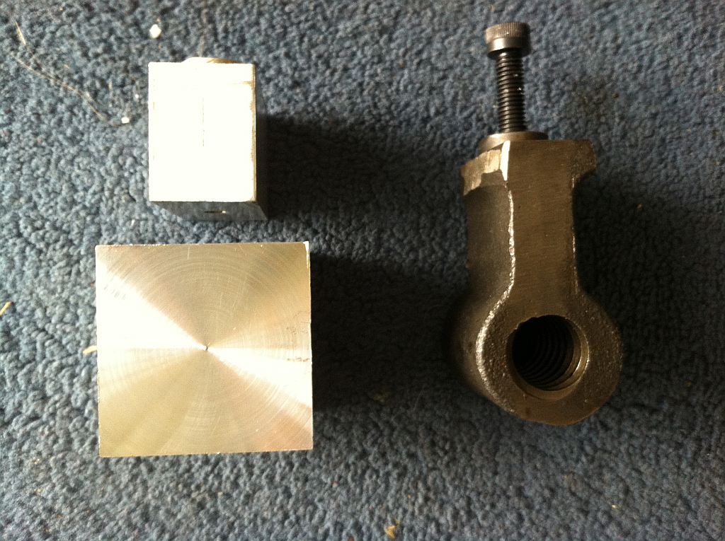
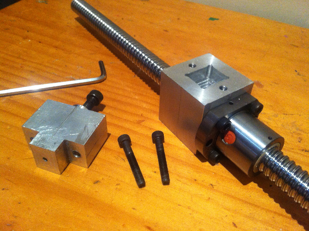
The first image shows both part A and Part B of the Ballnut holder. I was very happy with the fit of the peg into the pocket. It ended up being a firm press.
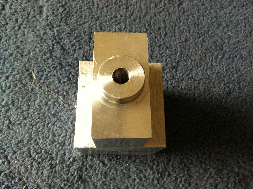
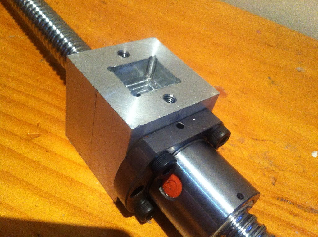
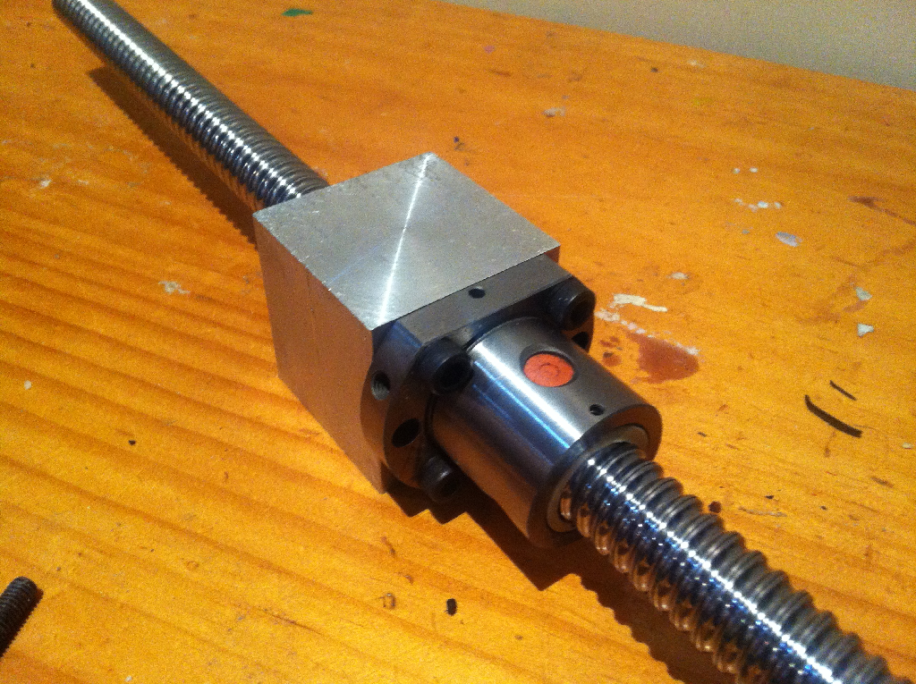
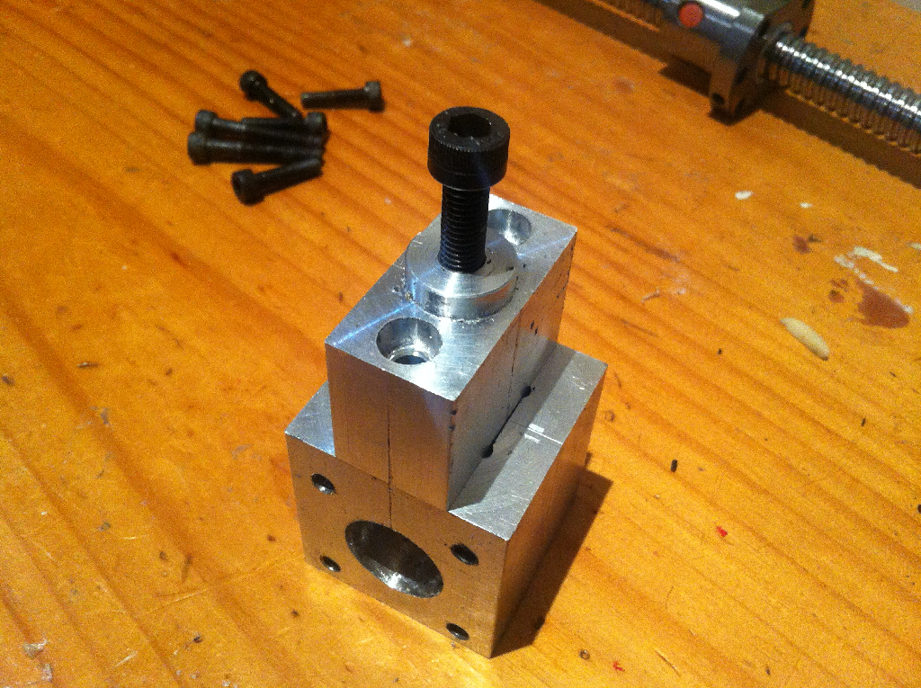
The next two images show the two parts bolted together.
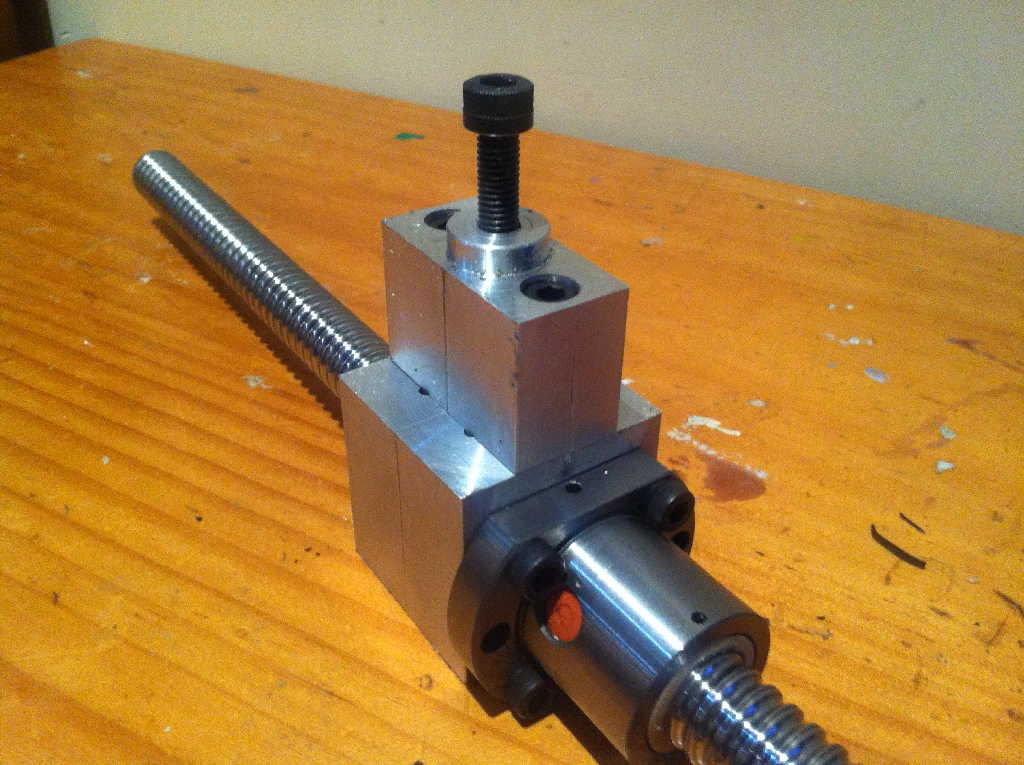
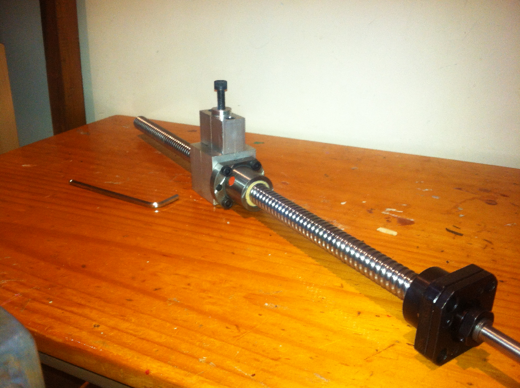
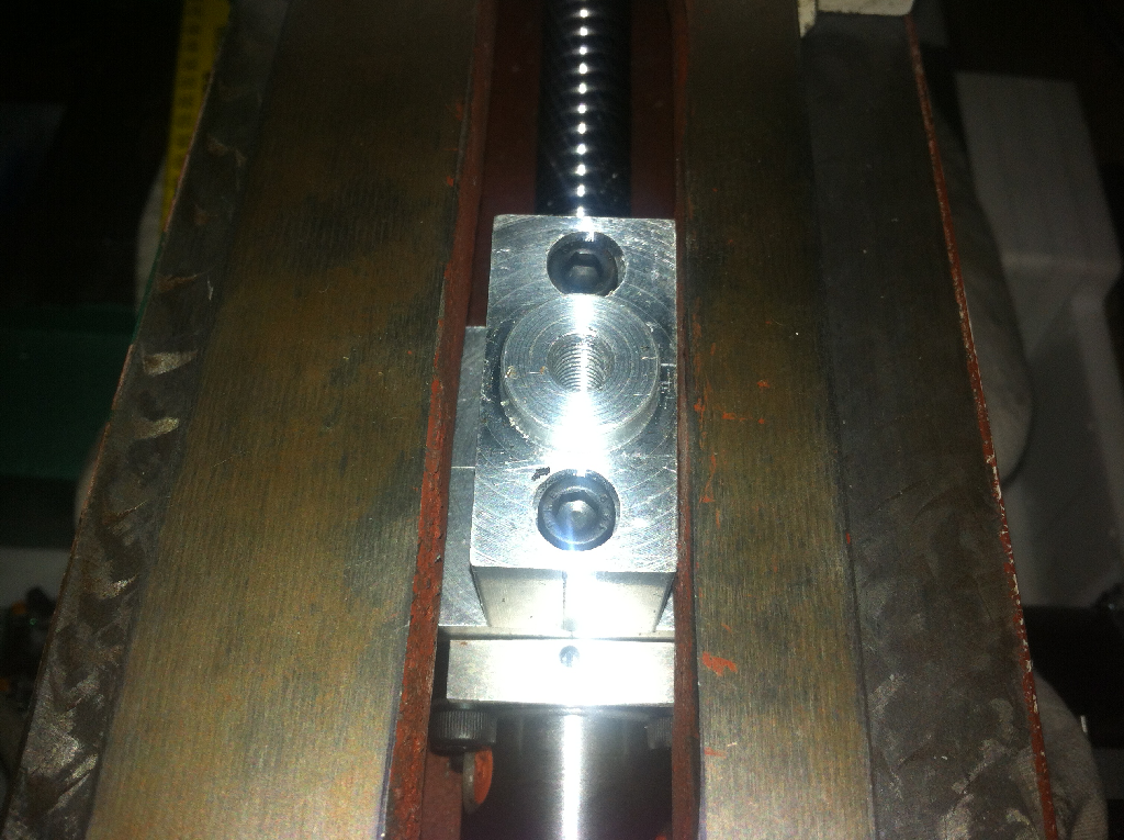
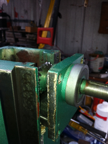
These images show the nut holder mounted to the Z-nut on the ballscrew.
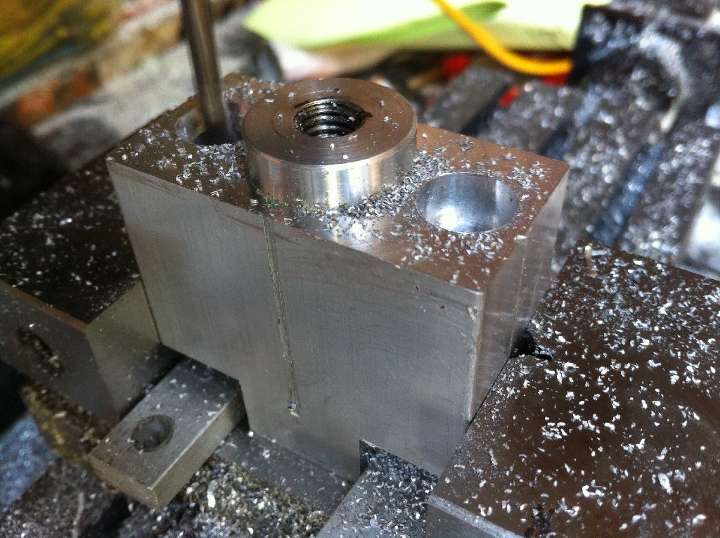
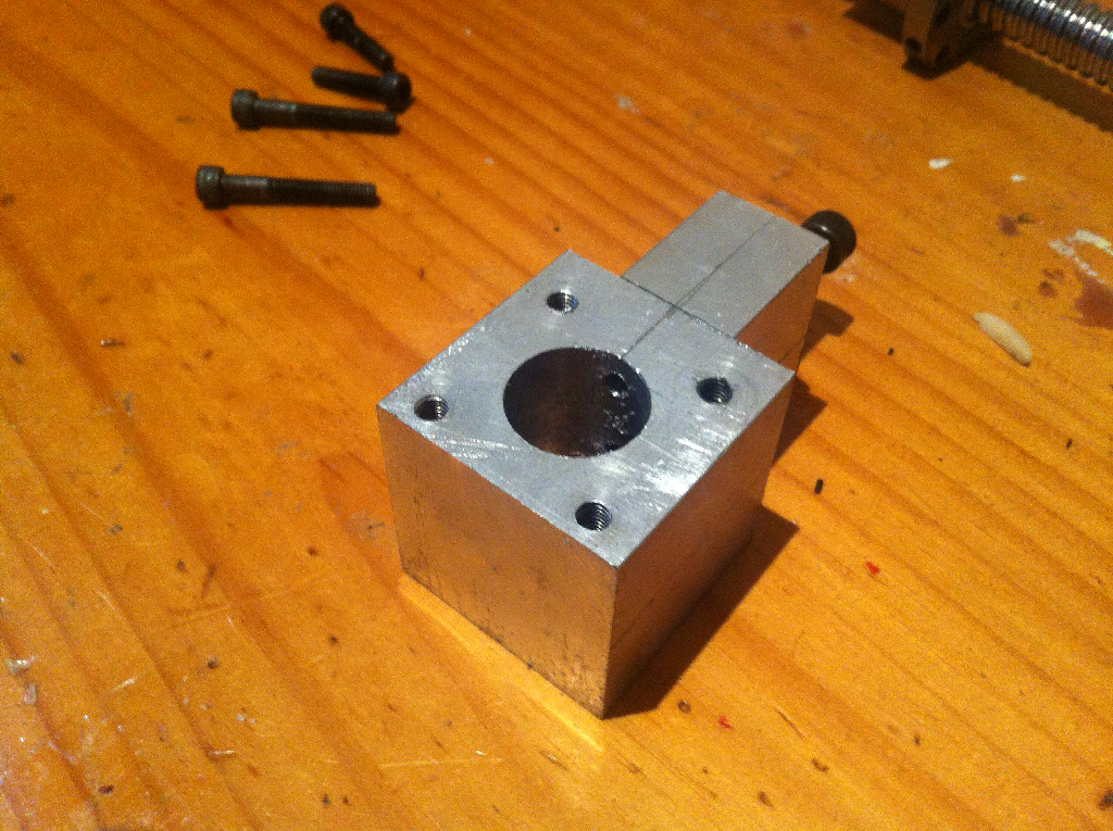
The last of the images shows the ballscrew clearance through 25mm hole in the nut holder.
The hole was drilled with a 25mm drill bit on the drill press.
![]()
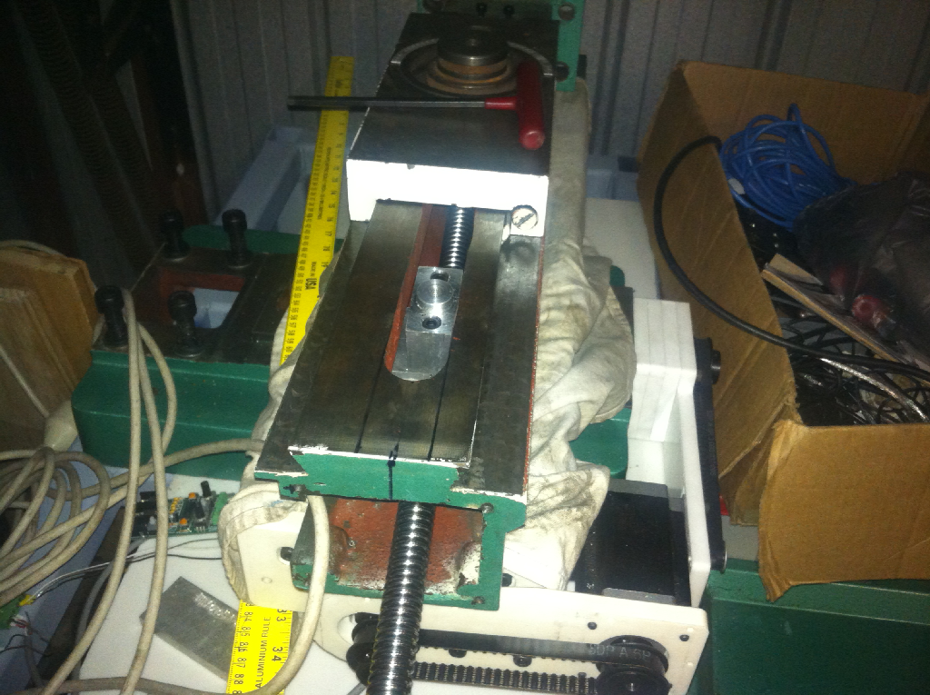
These two images show the Z-axis ballscrew and nut holder inserted into the column.
I'm really pleased with how it turned out as it is so quick to assemble the axis.
I still have a bit of work to do with respect to making the Z-axis top plate that holds the Z-axis bearing supporting the screw. It's going to be tricky as there are no real reference points.
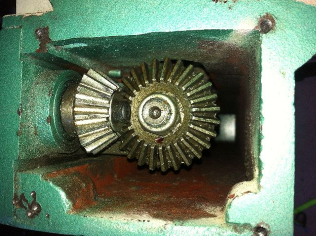
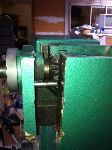
The column originally just had a thin sheet metal cap covering the top of the column as the original Z-axis was supported by a right angle bracket mounted to the side of the column that contained the crown and pinion gears plus the screw.
You can see how the poorly the holes holding the top plate were drilled. I'm thinking of filling them with cold weld filler before I drill any new holes.
Next is the Z-Axis top plate. My plan for the top plate is to make a replacement plate for the side plate. This will be made from of 12mm aluminium plate.
I'll then make the top to sit on the top of the column. It will bolt to the column in the 4 corners of the column where the original top plate bolted to as there are welded gussets already in place for this.
Initially it will be bolted to the new side plate with 2 bolts as well as to the Z-Axis Dovetail section with another 2 bolts. I then plan to drill the 4 holes for the corner bolts.
The top plate will have all the holes CNC machined so I plan to use them as a guide when drilling the holes into the top of the column.
As with most of the parts I've made for the conversion, I'll make them out of 12mm Corian first.
This is going to be especially useful for the top plate as I expect a little trial and error in getting the location of the Z-axis bearing block hole into the correct spot.
The top of the dovetail slide will be a reference. I need to determine the gap between this and the surface on the underside of the Z-axis slide that the nut holder bolts to. Once I know this I should be able to determine the distance to the centre of the ballscrew based on the ballnut holder dimensions.
I then need to determine the centre of the slot in the column. Theoretically, this should be where the hole in the top plate needs to be. In the image you can see the marker lines where the centre should be.
I'll make the top plate, fit it, measure any misalignment, make another out of corian and refit. Hopefully the 2nd one should be spot on.
Once it is done, the final top plate will be out of 20mm aluminium plate.
TM20VL Mill CNC Conversion (Part 5)