The Y axis is coming along.
Once again it is measuring the sizes and mounting locations by measurement. What I doing is taking measurements with vernier callipers, then with the understanding that it is a metric machine and assuming that the dimensions are in metric, round the measurement to a reasonable values based on what I feel an engineer would have chosen.
So far it has worked out pretty well. The X_Axis end plates were spot on, The mounting holes for the plate were 160mm apart. The ballscrew centreline is 50mm below the mounting hole centreline. The ballscrew centreline is 15mm above the saddle, etc.
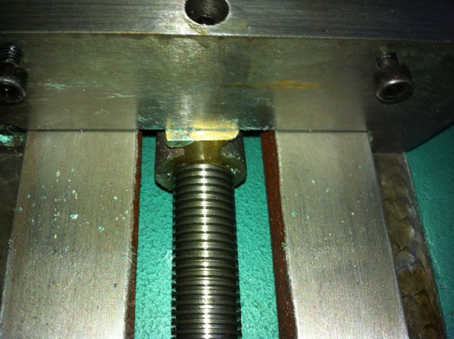
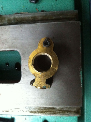
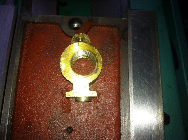
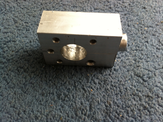
The Y-nut holder has a 15mm boss that locates into the saddle and is held there by a M8 capscrew. The original parts can be seen below.
For the new Y-nut holder, I used 25x40mm aluminium bar. It is just wide enough to slip down through the slot in the base.
Since the screw is 16mm compared to the 25mm one that came with the machine, the hole is the front of the base where the screw attaches to the bearing block has quite a lot of clearance for the new screw.
As the saddle extends a long way (40%-50%) over the front of the base I decided to take advantage of the smaller screw diameter and lower the new screw centreline by 4mm. This allows me to have more clearance and fit a larger pulley along with the pulley and belt cover without worrying about any binding resulting in reduced travel.
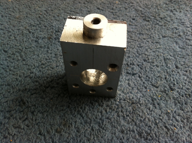
To make the Y-nut holder, I chucked the 40x25mm stock into the Taig 4 jaw chuck mounted on my 7x14 CNC lathe. Once the stock was centred, I turned the boss, drilled and tapped the M8 mounting hole.
While still in the chuck, I used the tool-bit to scribe the centreline down the side of the stock. This was to ensure that when the work piece was transferred to the mill I could easily locate the mounting boss centreline.
Once in the mill The centre hole and mounting bolt hole pattern was centre drilled. The bolt holes were then drilled countersunk and tapped for M5 bolts.
I then used a drill press to drill the centre clearance hole, stepping up in drill sizes until the 20mm hole was drilled.
Unlike the X-Axis ballnut which went smoothly, I had all sorts of chatter with the 20mm drill bit (previous drill was 1/2"), with the MT3 taper chuck holder dropping out of the quill, and/or jamming in the work- piece.
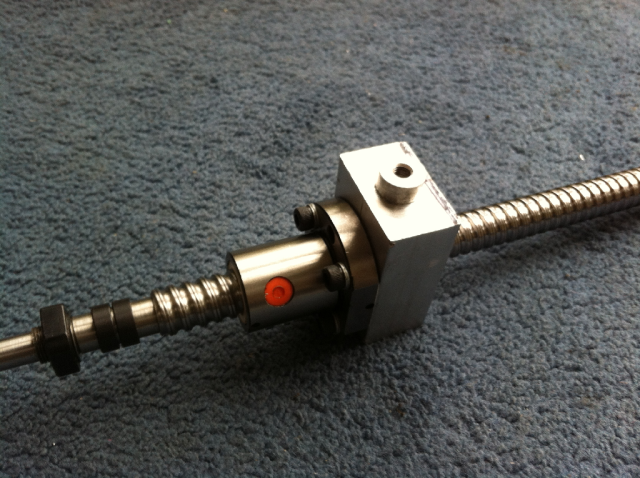
As you can see, I has to flip the ballnut over on the screw to mount it the way I need it.
Y-Axis Stepper Plate
A bit more progress on the Y-Axis.
I made up the following parts for the Y-axis over the weekend.
- Bearing block support
- Spacer
- Stepper plate
The Bearing block support is made up of two 12mm thick pieces of Corian. When I make the "Real" piece out of aluminium, I'll use a single piece 20mm thick, or two 10mm thick plates. The FK12 bearing block is 17mm deep, so having the bearing block support 20mm thick will reduce the extension on the front of the machine by 4mm.
You can see in the photo showing the ballscrew that I've left the clearance to reduce the bearing block support thickness.
The Spacer will also end up being made from 10mm aluminium plate as well in the final version.
The stepper plate will eventually be made out of 12mm aluminium plate as well.


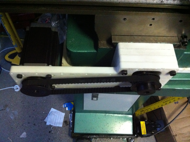
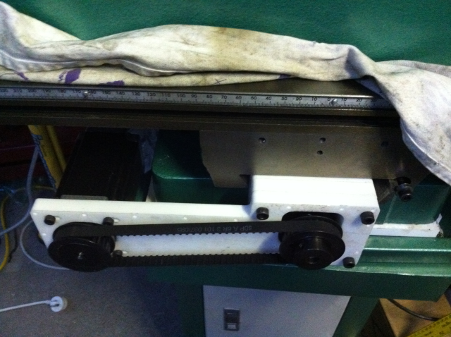

You can see from the photos that when the saddle is fully forward it projects right across the bearing block supports and stepper plate, with very little clearance. In fact you can see the saddle deflecting the belt
The photos show two 28 tooth pulleys as I messed up the belt lengths and I didn't have a belt the right length for the 20 tooth pulleys which I plan to use for a 1:1 drive.
Although 20 tooth pulleys will clear the saddle, they would not clear the inside of the cover that will fit over the stepper plate.
I'm thinking of trying 16 or 18 tooth pulleys for a direct drive. Hopefully there will be enough teeth in contact with the belt.
I also have plans to put an idler bearing onto the stepper plate to deflect the belt away from the saddle if I want to use the 28 tooth pulley for a gear reduction drive.
Its Alive.
I wired up a 387 oz.in motor on the X-Axis to a Gecko G540 with a 1:1 belt ratio using 20 tooth pulleys.
I am getting 8000mm/min or a bit over 300 in/min. I had the Z column laying on the table to provide a bit of moving mass.
I tried 9000mm/min but was getting intermittent stalls.
I still need to do a lot more testing, but its looking like I might stick with the Gecko G540 and the 387 oz.in motors.
TM20VL Mill CNC Conversion Z-Axis (Part 4)