I decided to start with the X-Axis as there were a few ideas I wanted to test. I've decided to make as many parts for the conversion out of Corian. Corian is a Dupont material used primary for kitchen benchtops. It machines beautifully and does not stress my Taig CNC Mill that I will be using to make the parts. The material I get access to is 12mm thick, and primarily comes from sink cutouts and the like.
I should be able to used these endplates to assemble the X axis, and set up the X-axis nut holder, which will be my biggest concern at the moment.
I'm using these ballscrew bearing blocks.
FK12 16mm BALLSCREW END SUPPORT BEARING BALL SCREW CNC | eBay
I haven't see anyone else use these on a conversion yet, and wonder why as they make the assembly a lot easier and quicker. My guess is that they are a little expensive, but in the scheme of things it is not too bad.
Last night, I made a prototype end plate for the X-Axis.
I drew it up in DraftSight, then loaded the dxf file into Sheetcam and created the G-Code.
The holes for the 6mm cap screws that fasten the end-plate to the table were drilled to 6mm, so it is a tight fit. I did this to see how accurately the holes in the table were drilled. The bolts fitted up very well, so they may have been machine/jig aligned and drilled. This is in contrast to the locating pins which were obviously hand drilled as the holes are not even perpendicular.
Later on it may be necessary to increase the clearance on these holes so that some slight adjustment is available. That is also the reason that the countersink diameter on these holes is quite large.
If you notice the fit, the top of the side plate is slightly below the table sides. I'm not sure what this means in terms of fit. When I measured up the original plate. The lead screw centre appeared to be 50mm from the top of the plate, and the mounting holes appeared to be 25mm below the top of the plate. The mounting holes were 160mm apart. These were the dimensions I used as I figured that the mill was built of a blueprint somewhere and it was logical to use these dimensions.
The FK12 bearing block is held in with four M4 bolts.
I also put in four holes tapped for M6 bolts. These will be used to mount the plate that will hold the stepper or servo motors. The plate will have elongated holes that will allow me to tension the timing belts. There are holes either side of the centre as I haven't decided yet which side of the table I'll be mounting the motors.
The next step is to make the plate for the FF12 bearing block. It requires a slightly smaller hole.

Below are images for the ballscrew dimensions. I plan to send these to Chai from linearmotionbearings2008.
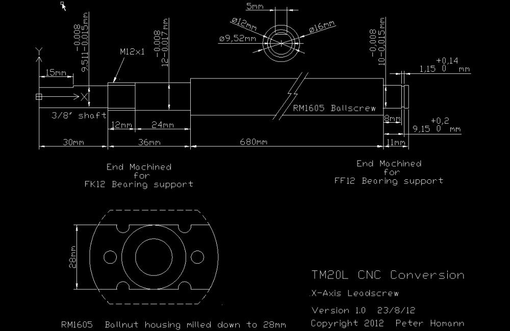
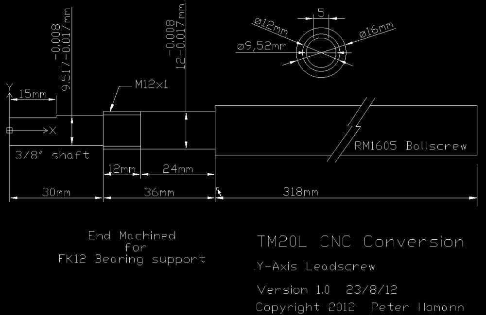
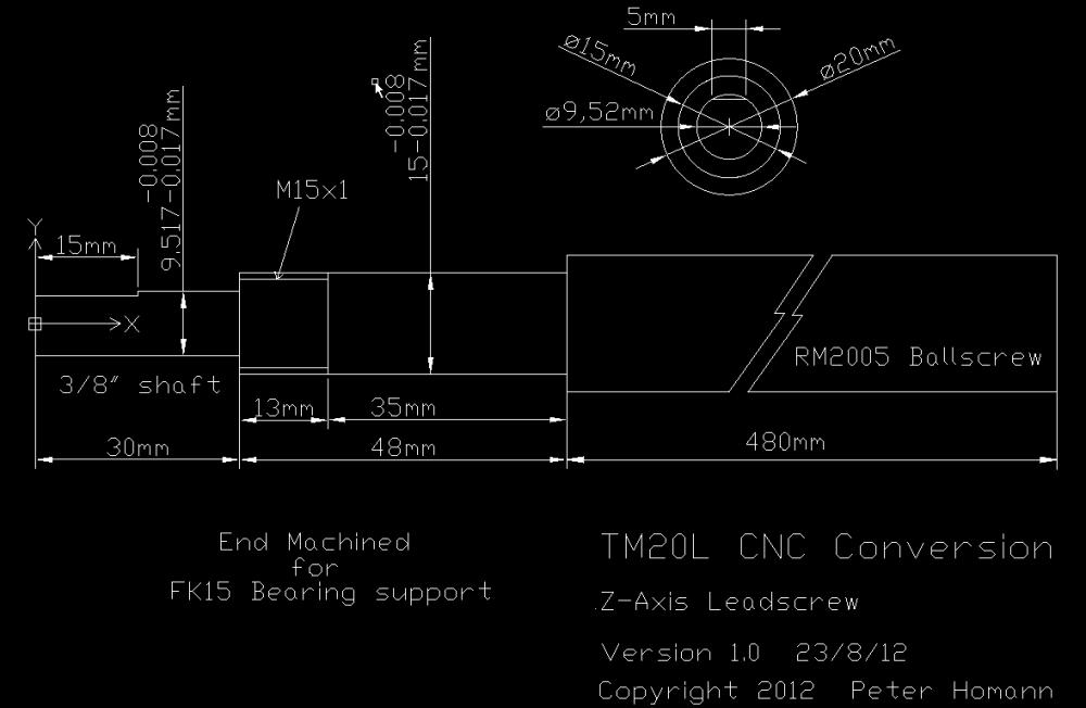
X-Nut Ball holder
I've been working on the X-Axis ballnut holder. I've finally realised that my mill is based on the RF series. .Maybe it should be called an RF20. 
It's slow going working on a 40mmx40mmx70mm piece on aluminium on my Taig mill.
The X-nut holder will be bolted from underneath as this is the only way I can see that the alignment can be adjusted for.
Also, because of the low profile and lack of headroom, the hole in the nut holder will only be 20mm to clear the screw. The nut will not pass through the holder but be bolted to it. I can do this as the nut holder is fastened to the centre of the saddle.

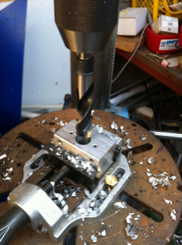
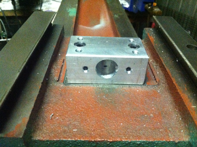
Below is an image of the X-Nut mount. Just finished drill the clearance hole for the ballscrew.
The 20mm Drill bit make quick work of the aluminium.
The X nut holder has 4 threaded mounting holes. The bolts come from the underside of the saddle. The bolt holes in the saddle will have a little clearance for alignment adjustment.
For the initial alignment, the table is laid upside down on a bench and the saddle with the nut holder bolted loosely to the saddle put onto the table. At this stage the nut and ballscrew have already been bolted to the nut holder.
The table end plates are mounted and everything is aligned and tightened.
Once aligned, the end plates are removed and the saddle slid off the table and the ballscrew and nut unbolted from the nut holder.
The saddle can then be mounted to the base and right way up and the table then mounted back onto the saddle.
Once I mount and align the nut holder to the saddle, I shouldn't have to touch it again. That said, I still have to do the Y-nut holder , so the X-nut holder may need to be removed to facilitate the making of this.
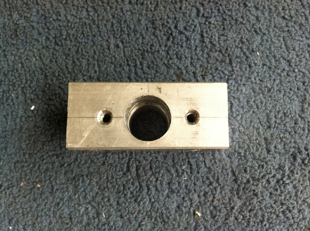
I've finally made some progress. The X-nut holder is done. Unless I've made it a mistake.
The holder is 70mmx40mmx31mm. There is a 20mm clearance hole for the ballscrew to pass through.
The ballnut is attached via two M5x0.8 bolts. The holes pass all the way through the holder so I can put another ball nut on the other end if I feel that it is necessary to have a zero backlash system.
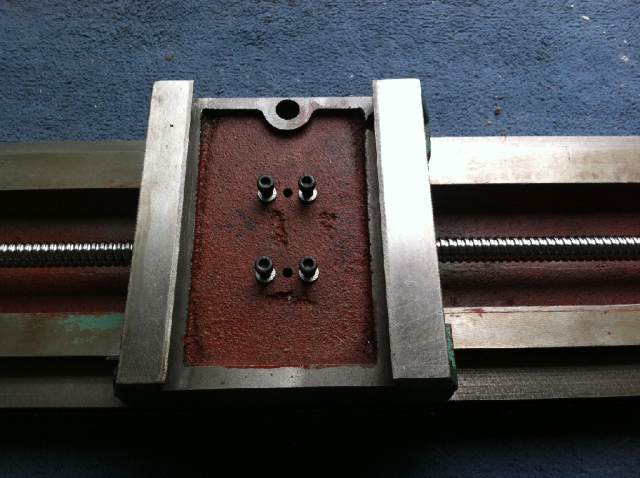
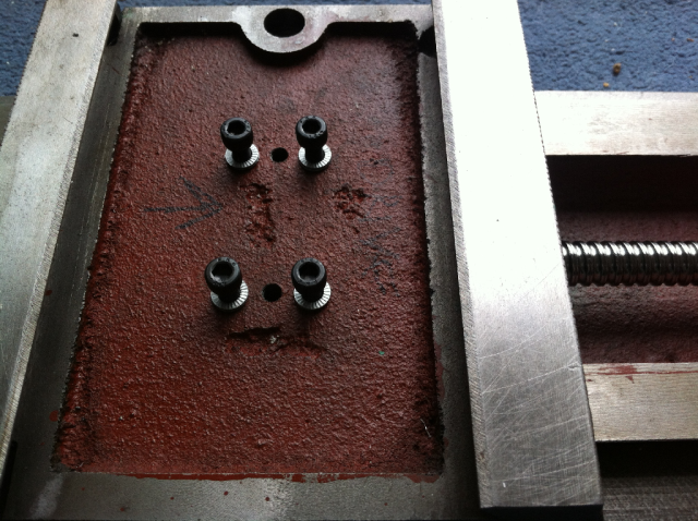
I accommodated the original nut's M6x1 mounting bolts. They are on a 50mm pitch. I plan to attach the holder with four M6x1 bolts from the bottom. That way I can adjust the alignment when the saddle is on the table.
You can see the centre punched marks for these mounting bolts in the saddle.

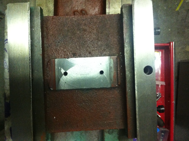
I was a bit worried about the clearance between the nut holder and the inside of the table. I shouldn't have been as there is a lot of room.
I installed the saddle onto the table upside down to test this, and also put on the endplate prototypes to see the fit. All I need now are the ballscrews to arrive and I can do a test fit.
You can understand why I want to fasten the holder with bolts from the underside. I plan to do all the alignment and adjustment of the X-Axis with the table on the bench like this.
As can be seen from the photos there is a lot of clearance. BTW, I need to get shorter bolts if you are wondering why they are protruding.
![]()
The Ballscrews from Chai turned up a few days ago. All looks good.
The ballscrew end bearings all slipped on with a nice fit. I had to turn the nuts end for end on each screw to suit the way I'm mounting them. though. I'm glad I asked for the extra balls as I did loose two.
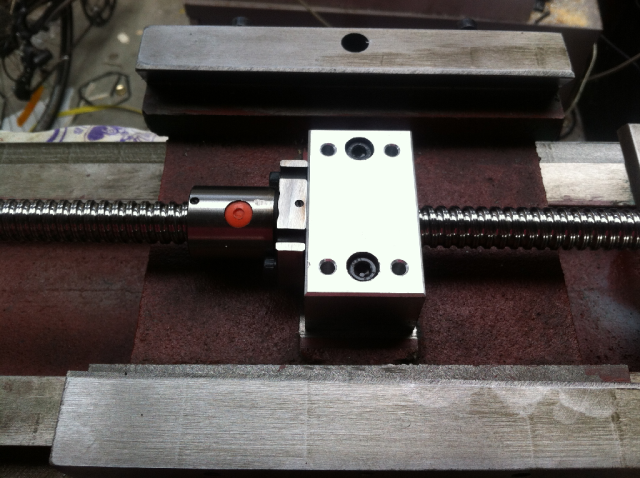
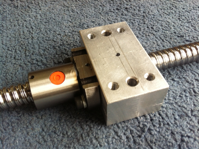
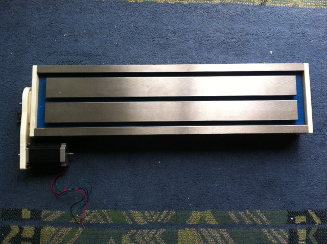
I took a quick shot of the x-axis ballscrew mounted onto the saddle.
When I made the X-nut mount block the centreline of the nut is 15mm from the top and 16mm from the bottom of the block. I did this as I wasn't sure if the screw centreline was 15mm or 16mm from the saddle surface.
From my measurements it seemed line it was 16mm. When I mounted it and put on the endplates it was obvious that 16mm was too high so I flipped the block over and it all lined up quite well. There is some ever so slight misalignment somewhere but that will be easily fixed by providing a little clearance in all the mounting holes.
I put on the end plates and used a power drill connected to the screw to run the saddle back and forth. It showed that the X-axis is going to work, so I'm very happy about that. Unlike the G0704 with its jam bolts, this mill does not have a nut mounting system that provides an alignment system. It all needs to be made accurately, which was not that easy since all the measurements had to be made and are not documented anywhere.
X-Axis Finished
The X axis is basically finished apart making the final parts out of aluminium.
I'm planning to run the mill using the Corian parts, using the mill to make the aluminium parts.
The mill will be used to convert itself to CNC.
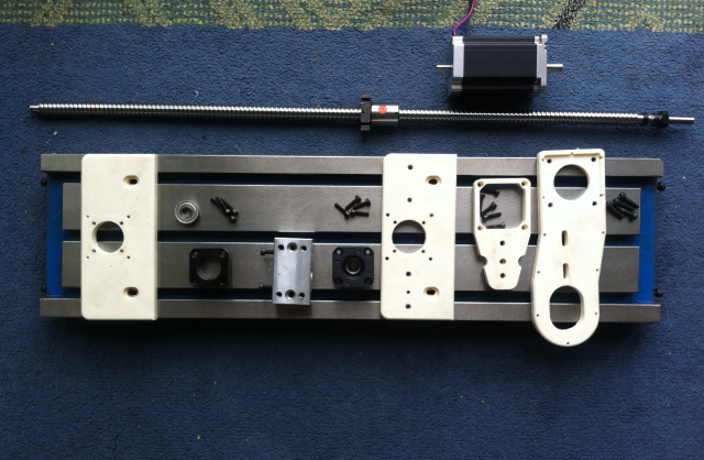
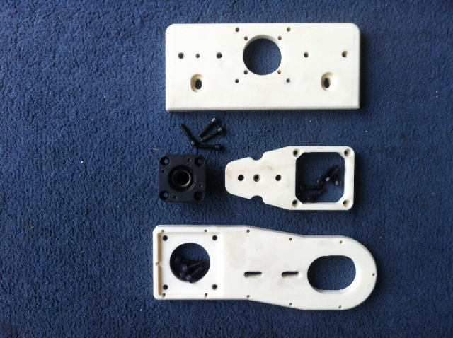
Below are the parts made and purchased for the X-axis conversion.
The first step is to screw the X-axis ballnut to the nut mount. As can be seen the nut itself does not go through the holder, only the ballscrew does that. This means that the hole can be smaller (20mm) and is just a clearance hole that can be drilled on a pedestal drill.
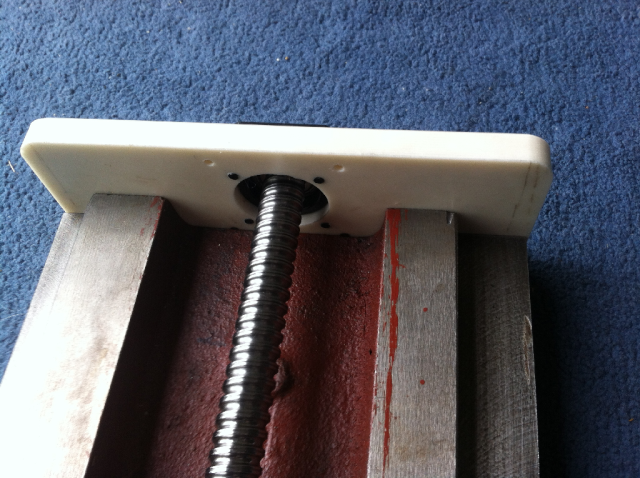
The ballscrew free end mount FF12 was assembled onto the endplate. The 4 tapped holes around the FF12 are to mount a bearing cover if needed.
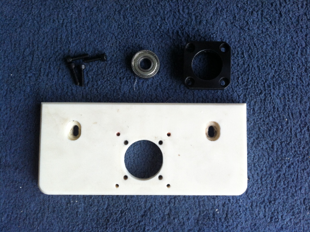
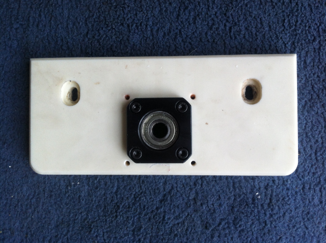
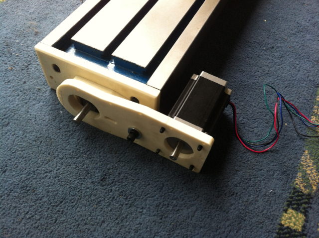
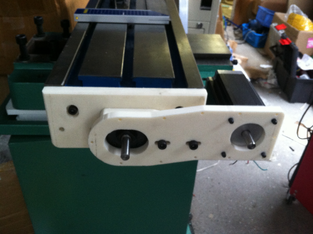
The fixed end mount end is a bit more complicated as it need to also accommodate the stepper motor mounting plate. As can be seen the FK12 is mounted to the endplate, a spacer plate is then attached, then the stepper plate. And finally the stepper motor is assembled onto the endplate.
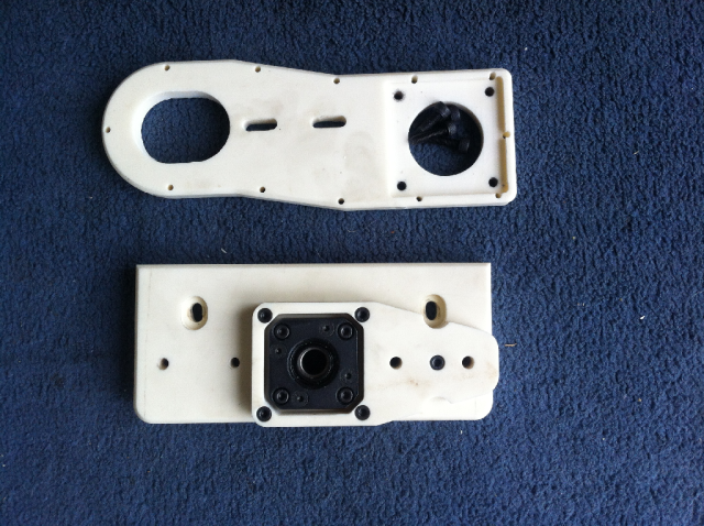
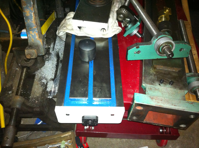
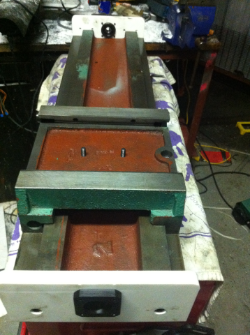
The next step is to assemble all the parts onto the table. These images show the trial fit of the endplates and ballscrew to the table.
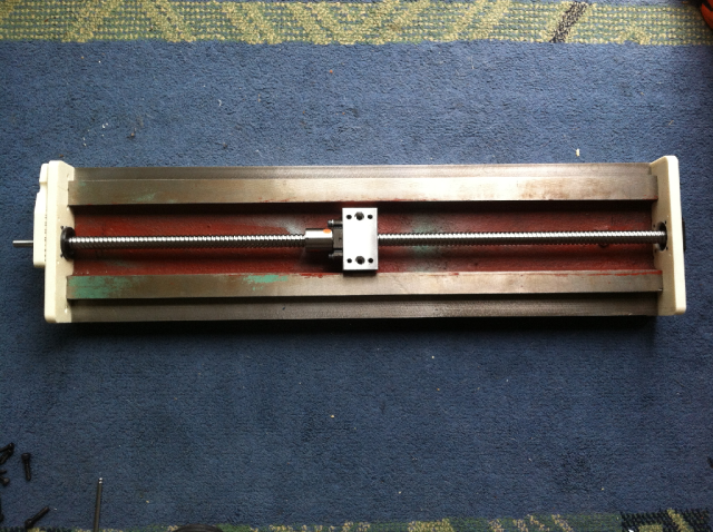

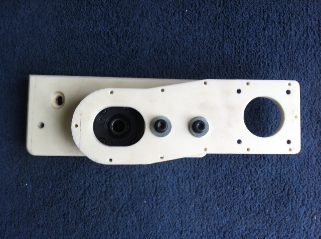
The next thing to do was to mount the table onto the saddle.
The ballnut mount is positioned by just taking up the 4 bolts without tightening them. Then the saddle is wound fully to one end and the endplate is aligned, then the saddle is wound to the other end for the remaining endplate. Once free movement is obtained across all the table range of movement the nut holder is finally fastened assuring alignment.
The endplates are then removed and the ballscrew nut unscrewed from the holder (but remaining fastened to the saddle) as the table needs to be taken off the saddle to gain access to the Y-nut holder.
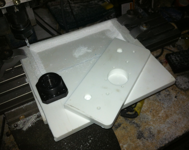
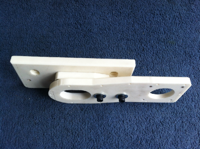
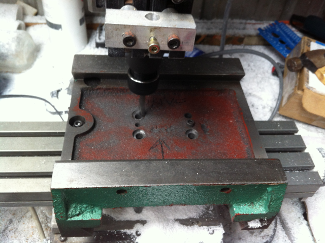
The middle image shows the countersinking of the bolt holes as there was insufficient clearance to clear the tip of the saddle when the table is fully forward and over hanging the saddle. It only needed less than 1mm but I countersunk down 2.5mm to be sure. As can be seen I bolted the Saddle to the Taig mill table by a couple of the existing holes. Cutting the cast iron of the saddle did not seem to stress the Taig mill at all.
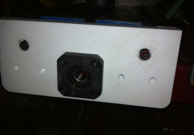
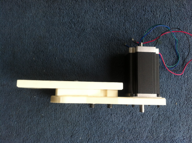
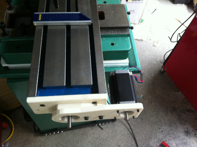
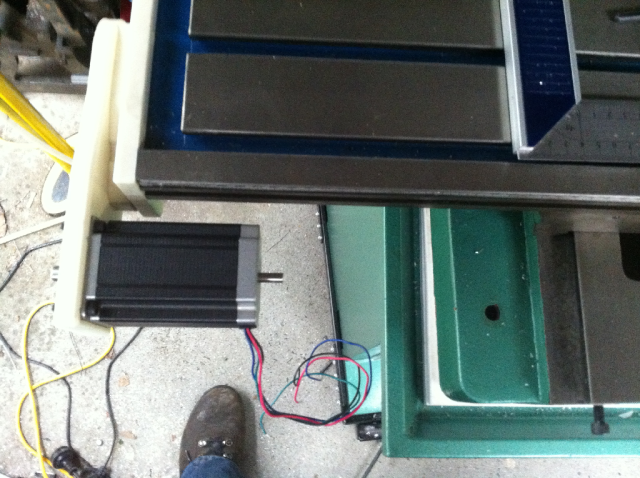
The next step was to test the stepper motor mounting onto the table while mounted onto the mill saddle and base to check the clearances.
All looks good so far .
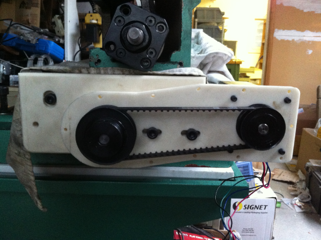
The following images show two of the three pulley set-ups I intend to try.
The 1st is a 20 to 28 teeth set-up giving a ratio of 1.4:1 using a 570 oz-in motor.
The 2nd is a 14 to 28 teeth set-up giving a ratio of 2:1 using a 387 oz-in motor.
I also have pulleys and belts for a 20 to 20 teeth set-up giving a ratio of 1:1 using a 570 oz-in motor.
All the pulleys are steel XL flanged pulleys. Not sure why I chose steel over aluminium. Maybe they will be more durable.
I'm hoping that the 2:1 setup with the 387 oz-in motor will be adequate. That way I can use a G540 as the stepper driver. I think it will be Ok.
With this setup;
5mm travel per rotation of the ballscrew.
200 steps per revolution of the motor
2000 steps per revolution of the motor using a Gecko 10microstep drive.
4000 steps per revolution of the motor using a Gecko 10 microstep drive and a 2:1 pulley ratio.
This ideally equates to;
A resolution of 5mm/4000 or 0.00125mm per step (0.0492 thousands of an inch)
An accuracy of 5mm/400 or 0.0125mm/step (0.492 thousands of an inch)
A 60ipm feedrate requires the stepper motor to rotate at;
60 ipm = 60*25.4 = 1524mm per minute
that is: (1524)/5 = 304.8 revs/minute
and with a 2:1 ratio 609.6 rpm
which is 609.6 *2000 /60 = 20,320 steps/sec
600rpm should be ok for the stepper but we will see. My taig mill rapids are set at 60IPM, so with the 20tpi leadscrew, the steppers are running at 1200 rpm. If it is in the torque delay area, the gearing will become less effective.
As to rapids of 60 ipm, I know there are lots of conversions that run a lot faster. For me 60ipm should be fast enough.
I really want to see if these mill conversions can be driven by the G540.

So that's about it for the X-Axis.
TM20VL Mill CNC Conversion Y-Axis (Part 3)