This is the start of a journey. I've had a Taig CNC mill for over 10 years now and it is a fabulous machine. I was after a larger machine and the Grizzley G0704, BF20 or Sieg X3 seemed popular choices.
If all turns out well I'll should be able to provide a nice controller kit for this type and size machine.
The G0704 is not available in Australia. The X3, is as are a number of BF20 style machines. In the end, I chose a TM20VL from Titan Machinery. It looks similar to the G0704 and the BF20L but does have some differences. I could have got a BF20L for less, but I was not sure of the quality. Also I wanted an R8 spindle so I could use TTS tooling.
I'm planning to do the conversion following the CNC Conversion DVD by Hoss. Obviously it depends on how close the machine is to the G0704.

Getting it Home
The TM20VL has the following Specifications:
- Spindle taper R8
- Spindle travel 50mm
- Quill diameter 60mm
- Table size 700mm x 180mm
- Table travel (longitudinal) 550mm
- Table travel (cross) 180mm
- Max. dist. spindle to table 360mm
- Max. dist. spindle to column 185mm
- Machine depth 580mm (to front handle)
- Machine height 930mm(head fully extended)
- Machine height incl stand 1730mm
- Head tilt 90º both ways
- T-slots 3 slots, 10mm studs
- Range of speeds 0-2500 RPM
- Motor 800W BRUSHLESS DC, single- 240v single -phase
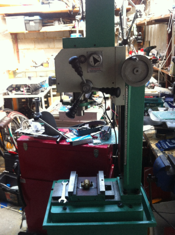
I picked up the machine from the shipping depot. I ended up using a scissor jack trolley to get it off the trailer. I raised the trolley to the height of trailer and shoved, pulled etc.
A few pics below.


The Inspection
It looks like a new top plate with the bearing mount for a ballscrew will need to be made.
I took a few photos of the X/Y ballscrews. They are 25mm diameter. The X screw nut mounts differently to the G0704 ones. You can see that in the photo. Hopefully there will be enough room
I also took of the left endplate from the X-axis. There is no bearing race, just a hole as a bush. A bit disappointing.
I'll make new endplates and I think I'll use this style of ballscrew supports.
1 set Fixed Side FK12 and Floated Side FF12 Ballscrew end supports CNC DIY | eBay


I took the end plate off to get a better look. Unfortunately the alignment pins are hand drilled at unknown locations as they cannot be reused.
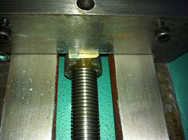
I then removed the table to see what is underneath. Below is what I've found.
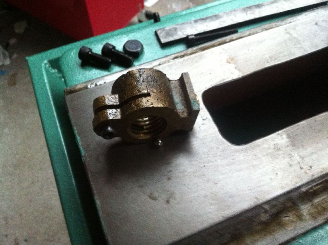
The X Nut is quite interesting. It is low profile which is not good. The screw is 25mm diameter so there is only 32mm clearance.
The nut has backlash adjustment. There is a 3mm ball bearing sitting in the nut. As the backlash adjustment screw is tightened the ball is forced against the screw.


Y-Axis Inspection
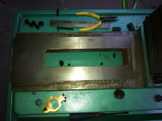
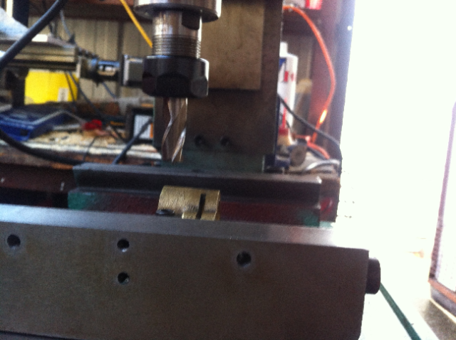
Removing the saddle to look at the Y nut was next.
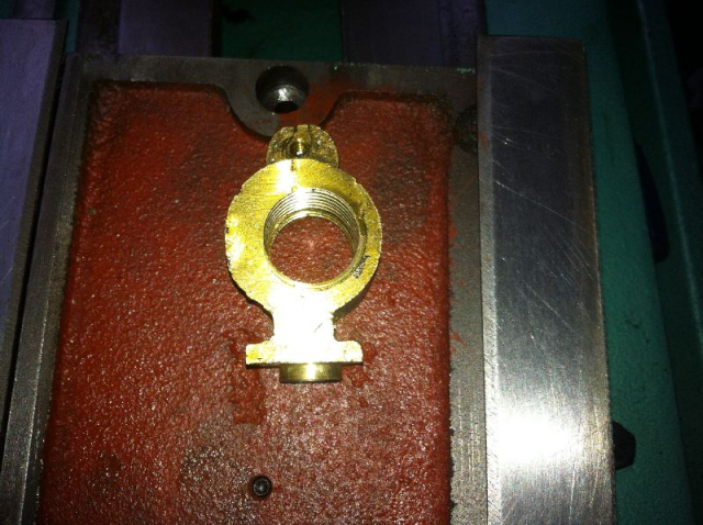
You can see the nut mounted to the back edge of the saddle. You can also see the bolt that holds the nut to the saddle.
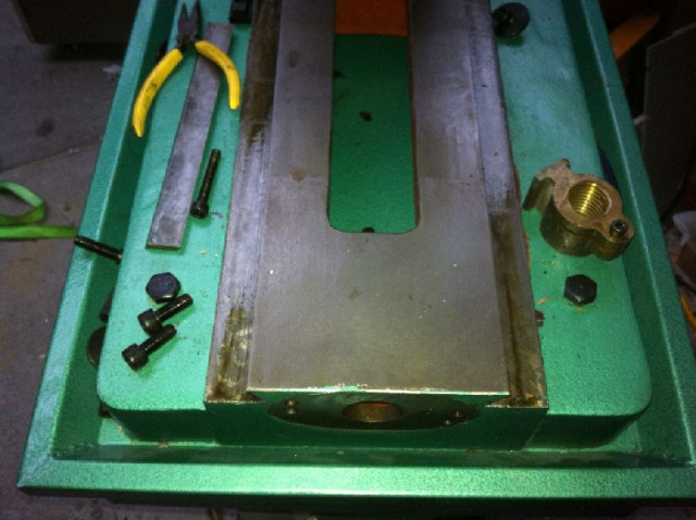
With the saddle removed, you can see the gap through the base. Lots of room for the Y-Axis. 
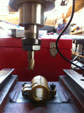
The Y-nut is interesting and has the same ball bearing backlash adjuster. The hole for the screw seems off centre but preliminary measurements indicate that it is on the centreline of the mounting boss.

Z-Axis Inspection
Before I dismantled the Z-axis I tried to understand a few of the issue I might face in the conversion.
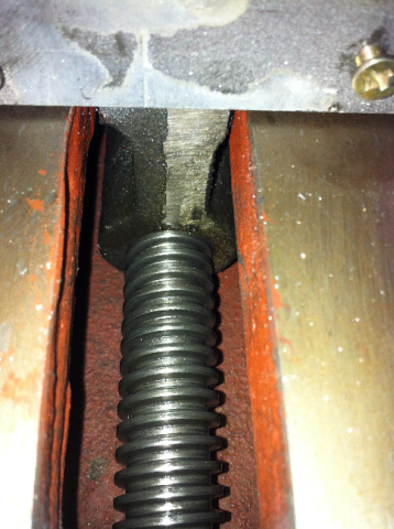
The Z-nut is right at the bottom of the head as can be seen in the first image.
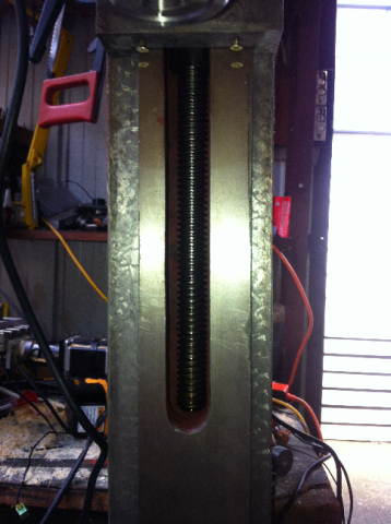
As can be seen in the next few images, there is a lot of Z-travel. And, when I put the Z-axis bearing on the top of the column, I'll gain about another 2". Already it can be seen that the top of the tead travels above the top of the column.
At the moment, the problem I'll likely face is that I won't be able to get the head as low as I like. The last image shows the head in the lowest position.
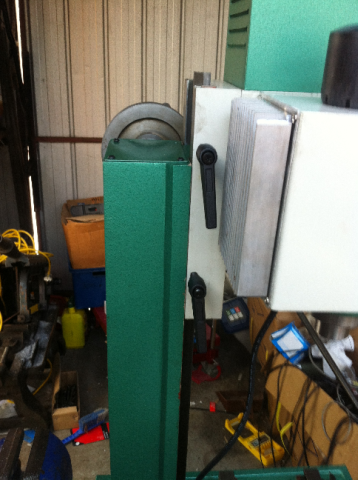

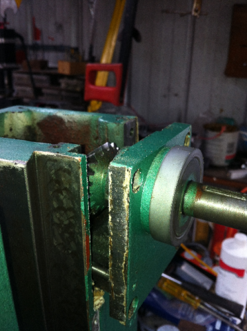
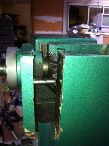
I started looking at what will be required for the Z axis conversion. The Z-axis on the TM20VL is quite different from the grizzly as the crown and pinion is attached an the angle plate that holds the Z-axis bearing.
To remove the Z-axis screw. The bearing plate need to be removed. It is bolted to the side of the column and also has a couple of dowel pins.
First the Z-axis nut is unscrewed from the head. The bolts holding the plate are removed and a soft mallet is used to knock the plate and the pins out off the column.
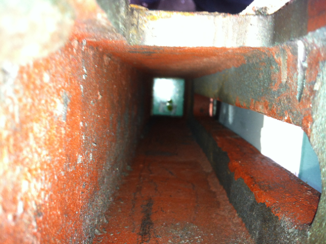
You can see where the bog (body filler putty) has flaked off during the removal.
The photos shows the inside of the column. At the bottom you can see the mill stand splash guard

I took a photo with the quill fully lowered. Even with this, I don't think it would touch the table. Especially if I was using a smaller bit.
And once converted to CNC with a timing pulley spindle drive, the quill will have to be locked in the fully up position.
The photo above shows were I plan to extend the slot so the the head can get lower.
A little more progress, that is if dismantling is called progress.
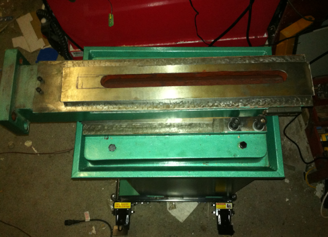
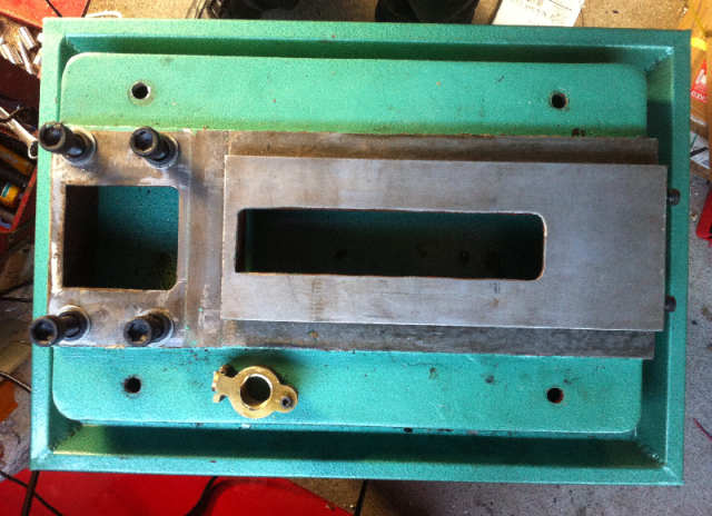
I've removed the column although I had to buy a 12mm Allen Key first. You can see where I plan to extend the cut-out.
As can be seen on the photo of the base below, I could also extend the Y-axis but as the Y-nut is at the far end of the saddle, it already extends over the end of the dovetail when fill extended, do for the moment I'll leave it as it is.
The last image shows the underside of the base.

TM20VL Mill CNC Conversion X-Axis (Part 2)