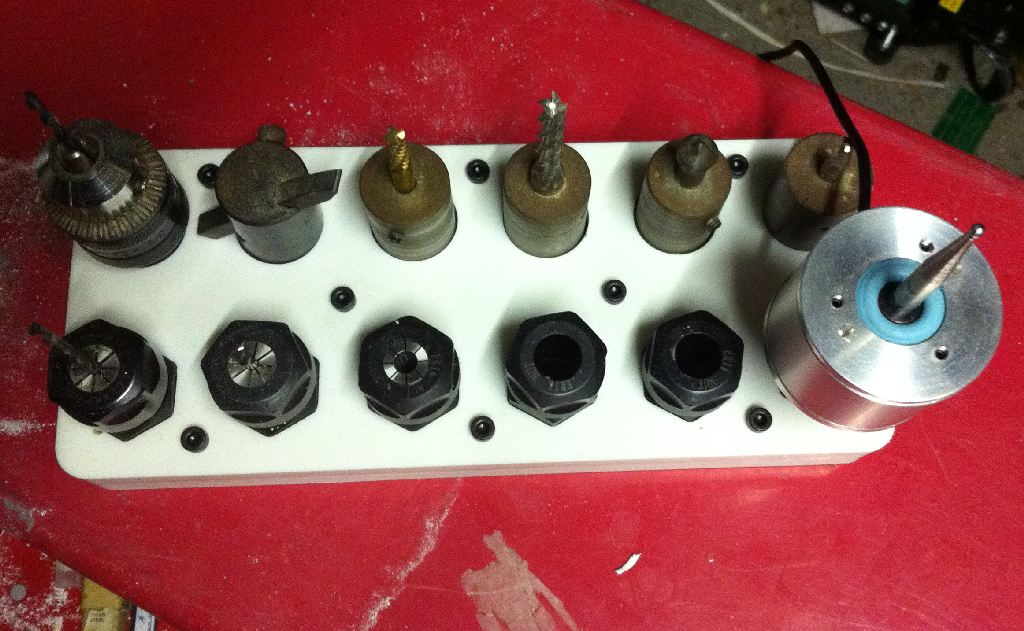
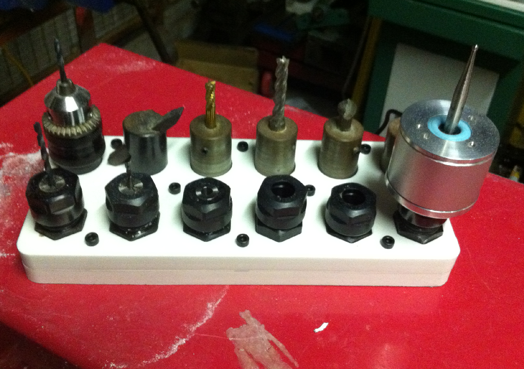
I recently purchased half dozen ER16 Collet adaptors form Nick at Carter Tools. They screw onto the standard Taig 3/4"-16 spindle to allow the use of ER16 collets for milling and work holding. I needed a Tool rack for them so I used the mill to build one.
Introduction
I want to set the collet adaptors up with their own tool bits so that I can then use them to get repeatable tool heights when changing tools. I already have some of the tool holders I made out of the blank arbor but the ER16 collet holders seem to be more accurate and more versatile.
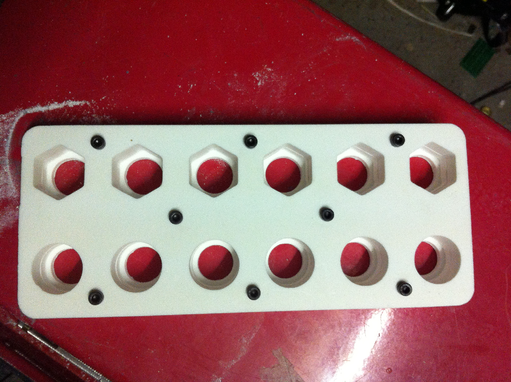
The tool rack is designed to hold 6 ER16 tool holders and 6 of the 1" arbor tool holders. The length of the rack is 240mm and was about the limit of the material that could be cut on the mill.
I only have 12mm thick Corian off-cuts. Corian is an ideal material for this type of work as it cuts very cleanly, yet is very kind on the tools. I use it a lot for prototyping.
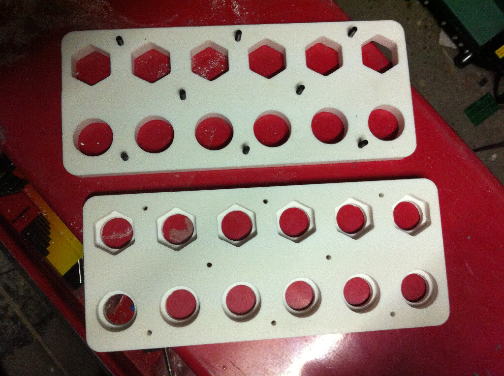
The basic construction is to use a stack of two pieces of Corian. The top piece will be cut through, the bottom piece will have the holes milled to a depth of 8mm and also have a small through hole cut as well. This is to allow and swarf to fall through the rack. The two pieces are bolted together with M4 cap screws.
CAD Drawing
I use DrafSight to generate my DXF drawings. I use different layer to identify the outlines that I'll be using for each of the cutting operations in Sheetcam TNG. This can be seen below.
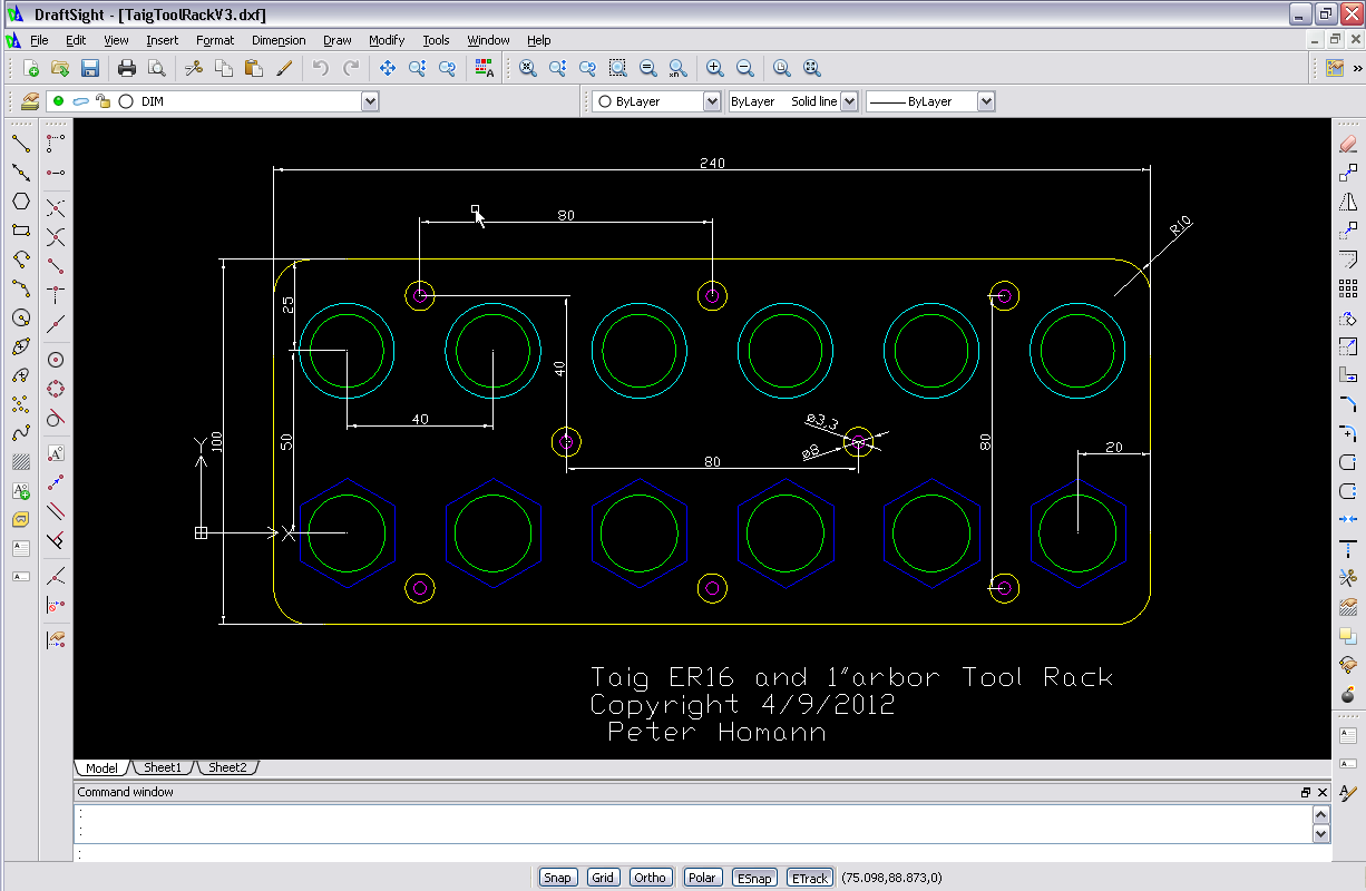
When doing the drawing it is important to think ahead about the cutting operations that will be required and to create layer that will be used for those operations. Giving the layers meaningful names helps.
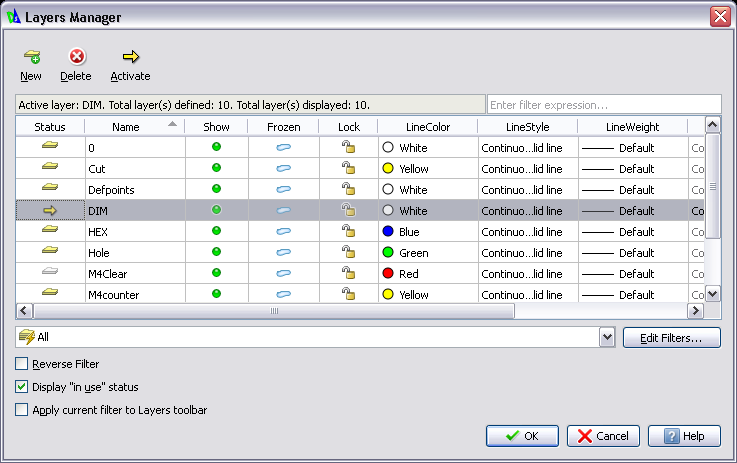
- The Green Layer is the through holes in both top and bottom parts
- The Blue layer is for the ER16 holders, cut through on the Top, Milled to 8mm depth on the bottom.
- The Aqua Layer is for the 1" arbor holders, cut through on the Top, Milled to 8mm depth on the bottom.
- The Pink Layer is for theM4 cap screws. 4mm drilled on the top, 3.3mm drilled on the bottom (for M4 tapping)
- The Yellow Layer oround the mounting holes is milled to 5mm deep on the top for countersinking the cap screws
- The Yellow layer outline is to cut out the rack on both top and bottom.
CAM Process
I used Sheetcam TNG to produce the G-Code files for the top and bottom pieces. I use the same DXF file for the top and bottom part and just apply different cutting operations to them.
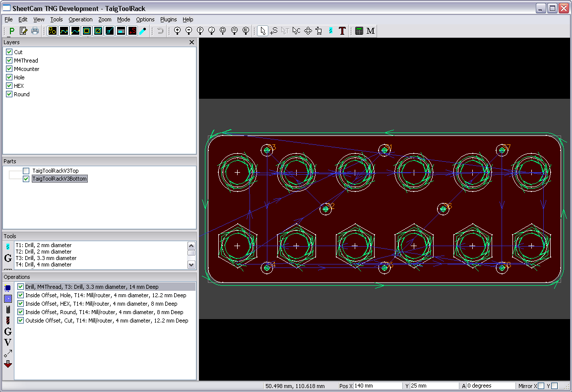
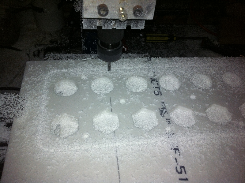
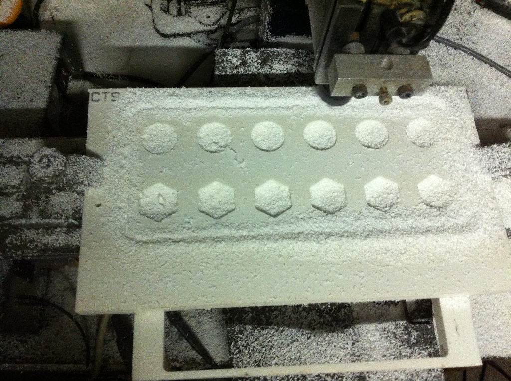
There are only two tools used to mill the Rack a 3.3mm drill and a 4mm slot mill. The feedrate I used was 400mm/min and a cut depth of 1mm per pass. Below are some images of the cutting in process and the finished rack.
CAD/CAM Files
These are the files I generated in producing the Taig Mill Tool Rack.
These files may be used at your own risk. I bear no responsibility for any damage or injury that may occur from using these files. The files may only be used for non-commercial purposes only.
Note: that the feedrates and cutting depths are quite aggressive due to the material I cam cutting. Be sure to adjust these to suit your machine and material you are using.
To download, Right click the link and use "Save As" from the Right click menu.

