This Article describes how I create fixture jigs for a Selective Soldering Machine that I use in the production workshop. It describes a process that goes from the PCB CAD artwork to a Drawing CAD package to Sheetcam then on to Mach3. THE process is similar to may processes that go from CAD to machined item.
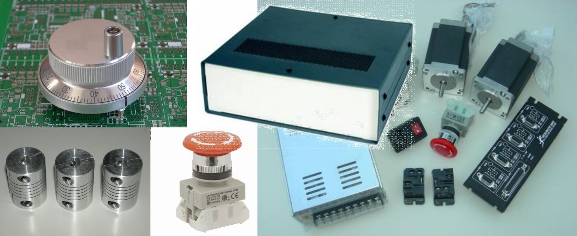
For a number of years I had a Fisnar Selective Soldering Robot. It was purchased as a 2nd hand machine and pulled out of a production environment. The Robot is basically a 3 Axis XYZ platform base with an automated soldering head module mounted to the gantry. Both the base and the soldering unit are programmed by a separate teach pendant. You need a third hand. :)
You program it in 2 parts. The head is programmed with all the different soldering cycles, including pre-heat, the amount of solder feed, rotation of the head, the soldering duration etc. These are called Blocks.
The 2nd part is to program the base XYZ with the other pendant. You move the head to a point, then select the soldering block you want to execute. You do this for every solder point. It works OK but is very tedious to program. When running the soldering tip moves down by a pneumatic actuator. The air pressure controls the contact force. You need to position the head so that the iron contacts both surfaces.
The soldering head has 30 different profiles. Each profile has 9 or so different parameters that define the soldering cycle. The base unit selects the cycle it wants and tells it to do it. Once it receives the acknowledgement back, it carries on.
To be fair, the machine does have an optional RS232 module that I don't have (of course). That would be the proper way to go. The pendant just contains a 2x20 lcd and a keypad. very rudimentary.
The robot works very well, surprisingly in fact. It is probably no faster per joint than hand soldering, but is a lot faster moving between the joints.
That's where it makes up time. Oh, and it can do it all day.
The video below shows the machine in use soldering one of the MB-02V6 breakout boards.
The biggest problem with teaching is that initially I made a rough fixture out of MDF to hold the parts and pcb. I then had to make a better system so that I can load one fixture while the other is being soldered. I've now make a number of more accurate and durable jigs out of Corian. Of course I need to reprogram the unit for the new jig. A bit over four hours to do the manual reprogramming. Because of the large amount of effort required to reprogram both pendants, I plan to convert the machine to run from Mach3. That way I can automate the G-Code generation from the PCB CAD files.
Selective Soldering Jig Manufacturing Process
The process I use to make the new jigs is;
PCB artwork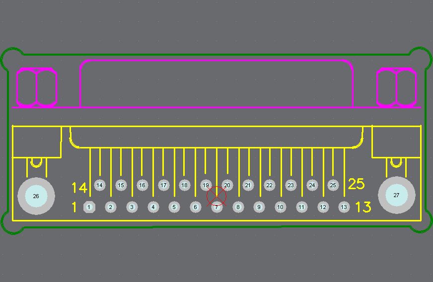
In the PCB package I use a mechanical layer for defining the cut-out areas for the jig. Each part in the pcb library that need a clearance cut-out has it defined on this layer.
You can see the Green cut-out areas in the image of the db25 part.
I export this cut layer out of the pcb package as a dxf file and load it into a standard CAD drawing package.
DXF CAD editing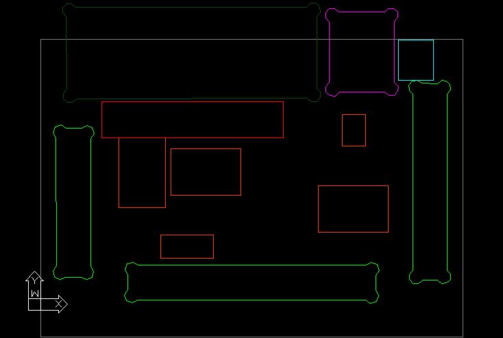
In the drawing package I then do any minor edits of the cut-outs, such as splitting some of the cut-outs into separate layers for loading into Sheetcam. The result of the editing is shown in image to the right. The different colours identify
the different layers that end up being different machining operations in
Sheetcam.
Sheetcam Processing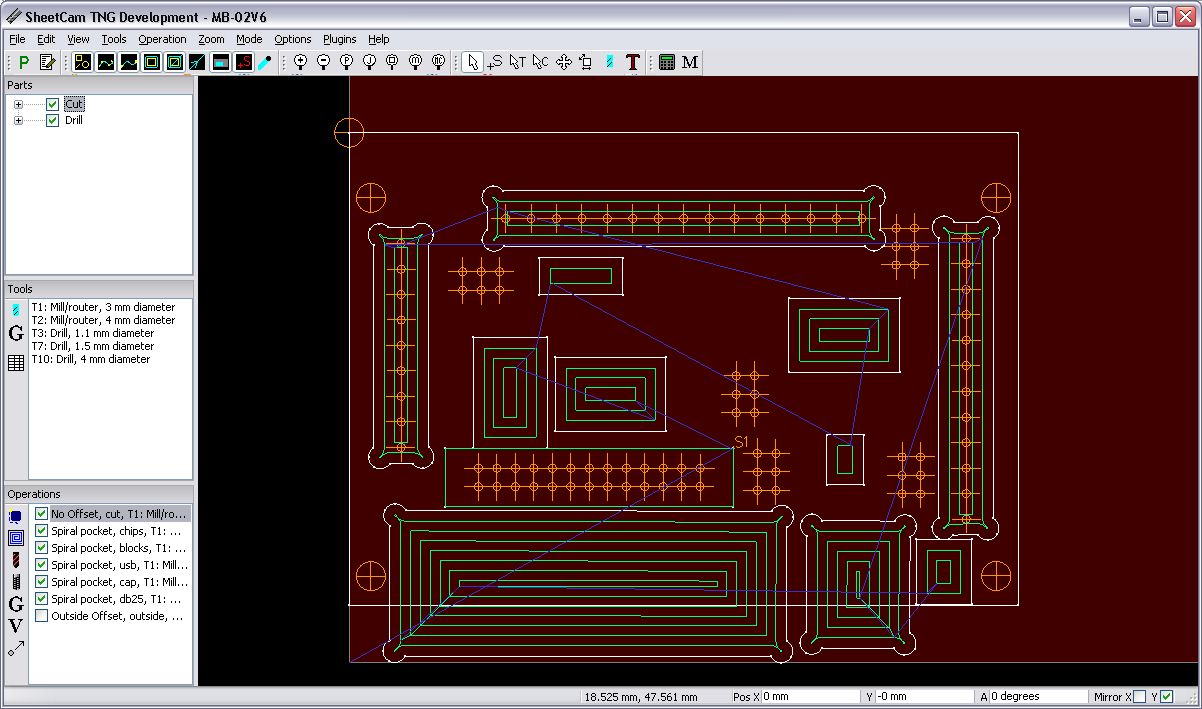
The DXF file is then loaded into Sheetcam TNG. TNG has a windows version and Linux version. Most of the cutting operations are in inside pockets. The different operations for the inside pockets are for the different component heights. Some of this is trail and error. The goal is to get all the components to be at the height when mating with the PCB.
Also note that in Sheetcam, The "mirror Y" axis is also checked as the pcb is placed onto the components in the jig upside down.
I also load in the pcb exellon drill file. I use this for drilling the holes for the jumper pins and the IDC 26 connector. The cut-out for the IDC26 is with no offset, so as to cut the clearance for the box header sides.
I produce 3 G-Code file from Sheetcam;
1. Drilling operations - This is for the 4mm locating holes, and the pin header clearance holes are 1.2mm. Some play in the 1.2mm holes is desirable to allow the components to jiggle a bit when placing the PCB onto the jig.
2. Clearance cut-outs. These are all done with a 3mm slot mill.
3. Outline cut-out. This operation is to cut the jig out of the coran sheet.
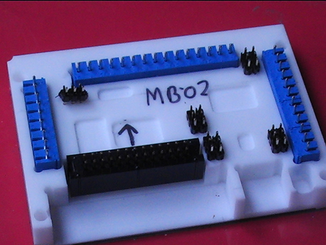
Machined Jig
The finished jig can been seen to the right. The arrow indicated the IDC26 orientation. Also visible are the recesses for the SOIC chip components.
Jig Loading
The pcb with the smt parts populated is shown in image to the right.
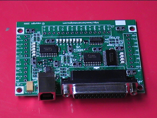
I first load the DB25 and USB connectors. They have locating tabs and are easiest inserted into the pcb rather than into the jig. The jig pockets for these are deep enough to provide support to the connectors.
The 3.5mm screw connectors and jumper headers are placed into the jig.
The PCB is then placed onto the components in the jig. The boards is supported by the components in the jig.
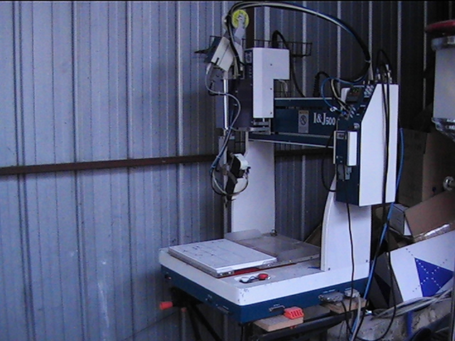
The Selective Soldering Machine
The selective soldering machine is made by Fisnar.
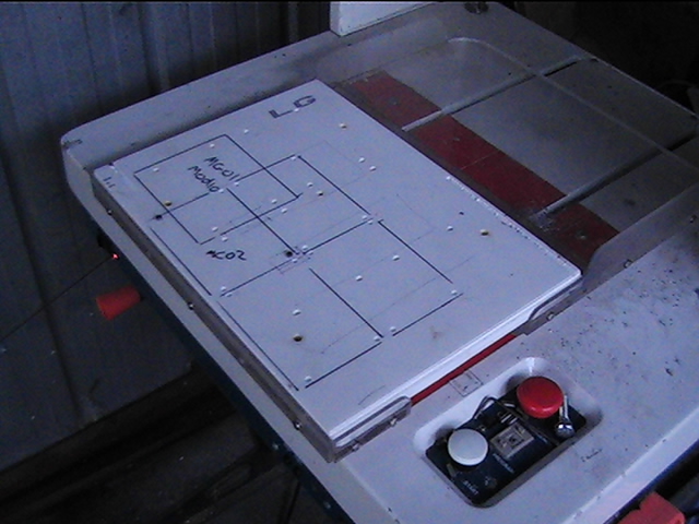
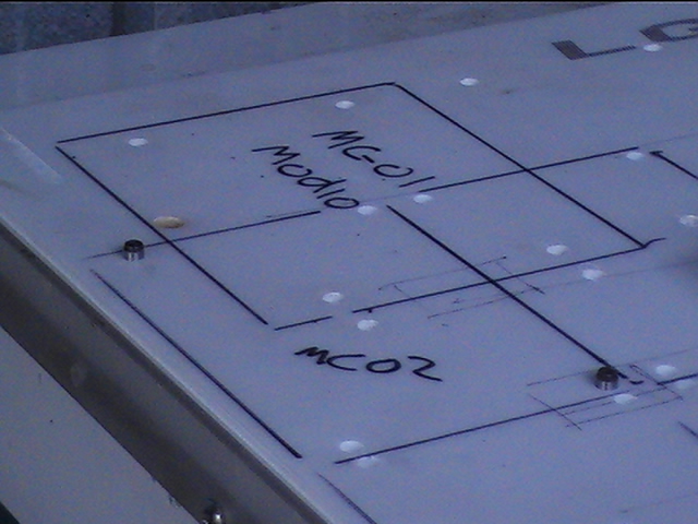
I've made a baseplate that fits into the machine and has 4mm dowel pins inserted that match the 4mm mounting holes in the jig. I can do different boards by changing the position of the dowel pins. You can see the location for soldering the ModIO board.

The loaded jig is then placed onto the dowel pins in the base plate ready for soldering.

The start button is pressed and away it goes. The video towards the top of this article shows the machine soldering the board.
The finished board joints are shown in the image to the right

The completed board ready for testing.