H-02 Solder Head Interface board
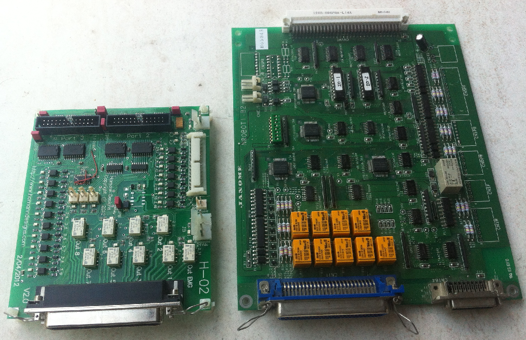
The next step is to start on the Solder head interface board. It uses signal relays for the outputs and opto-isolators for the inputs.All of the signals enter/exit through a 50-pin Centronics connector. Below is the new board on the left and the original I/O board on the right.
Once thing I did release when starting to look at the H-02 board , is that I need nine relay outputs, and 11 opto inputs for the expansion port. Then there is a 4 bit single digit program selector switch, cycle start button on the front panel.
I like to use the selector switch on the machine to select and load the GCode program. Not sure how easy it is to do this, but it should be possible.
Looking at the I/O requirements, a single 2nd port is not going to be enough to deal with all these signals.
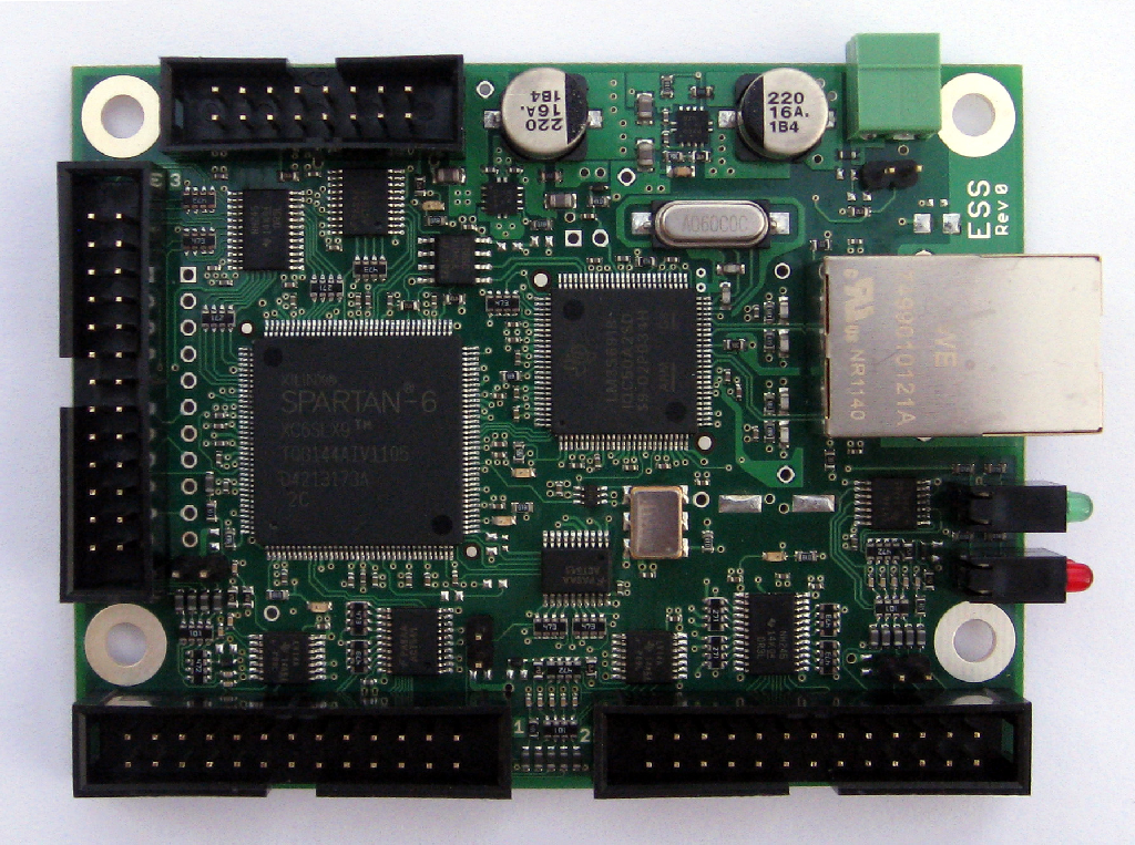
The solution I'm now leaning towards is to use the Ethernet Version of the Smooth Stepper. It has the equivalent of three parallel ports.
The board consists of 17 opto-isolated inputs and 9 relay outputs. Obviously this is too much I/O for a single parallel port and requires 2 ports to manage the I/O.
I already have port 1 dedicated to the stepper drive board that manages the 3 axis drives plus the limit/home switch inputs. As I needed three ports to deal with this machine the obvious choice was to use the Ethernet SmoothStepper which has 3 parallel ports on it.
Port 2 is used to drive the 9 relays plus accept the inputs from the base switches, etc
Port 3 has D2-D9 configured as inputs and deals primarily with the inputs from the soldering head.
As can be seen, the new board is a lot smaller than the original one.
I'm really pleased with this setup, and I don't think there are many other solutions to this problem that would be as economical as the Ethernet SmoothStepper.
As can be seen there is a hardware patches on the board. The soldering head has a "End" pulse or so I thought that is a short pulse to indicate that the operation has finished.The board design has a Flip-Flop to change the state of the output instead of a short pulse . I swapped the chip for a binary counter chip acting as a flip flop, thus the jumpers to do the re-wiring. In the end, I didn't end up using this signal as it appears to indicated that the command was received but not necessarily finished.
The soldering unit also has a ready/standby output. This is the signal that I'm using to determine when the soldering head is performing a block soldering command. In the normal state the "Ready"signal is active. Once the head starts the soldering cycle, it goes inactive until the operation is completed and it is ready to accept the next command. This signal also goes inactive if the iron is not up to temp or a fault occurs such as running out of solder.
Soldering cycles via Mach3 M6 Tool-Changes.
As previously described, the soldering head has its own pendant that is used to program the parameters for the 31 different soldering cycles called blocks. The block to be used is selected by 5 output lines that represent the binary value of the selected block.
I've created a M6Start Tool change macro that I use to select the block number. Tool 1 will select Block 1, Tool 2 selects Block 2, etc. The macro is listed below. The macro is quite simple, it just sets/resets the 5 relays based on the tool number.
Because the soldering iron tip does not align with the C axis rotation, I'll need to apply some X/Y offsets so that the tip is correctly positioned for the soldering joint location.
My current plan is to see if I can use the tool wear and Tool height values in the tool table, using them to set the X/Y values in a G52 X Y offset which will occur in the Tool change macro.
' Fisnar Soldering ToolChange Macro
' --------------------------------
'
'The tool number is used to select the soldering cycle that the head is to
'perform. There are 31 different soldering cycles that can be chosen. The
'parameters for each cycle needs to be programmed into the head by a separate
'pendant that comes with the head. The Toolchange macro then just selects which 'cycle is selected.
'Mach3 outs used to select the 5 bits defining the cycle number. Block1 is the LSB
const BLOCK1 = OUTPUT2
const BLOCK2 = OUTPUT3
const BLOCK3 = OUTPUT4
const BLOCK4 = OUTPUT5
const BLOCK5 = OUTPUT6
'Get the new tool number
tool = GetSelectedTool()
'Deativate all outputs
DeActivateSignal(BLOCK1)
DeActivateSignal(BLOCK2)
DeActivateSignal(BLOCK3)
DeActivateSignal(BLOCK4)
DeActivateSignal(BLOCK5)
'Turn on outputs as required for the selected tool
select case tool
case 1,3,5,7,9,11,13,15,17,19,21,23,25,27,29,31
ActivateSignal(BLOCK1)
end select
select case tool
case 2,3,6,7,10,11,14,15,18,19,22,23,26,27,30,31
ActivateSignal(BLOCK2)
end select
select case tool
case 4,5,6,7,12,13,14,15,20,21,22,23,28,29,30,31
ActivateSignal(BLOCK3)
end select
select case tool
case 8,9,10,11,12,13,14,15,24,25,26,27,28,29,30,31
ActivateSignal(BLOCK4)
end select
select case tool
case 16,17,18,19,20,21,22,23,24,25,26,27,28,29,30,31
ActivateSignal(BLOCK5)
end select
'Set the current tool to the new one
SetCurrentTool( tool )
Initiate Solder Cycle using G82 Drill with Dwell code
The locations to be soldered come from the Excellon PCB drill files that are produced as part of the pcb artwork file set.
These files basically have a drill tool number and a list of X/Y locations where the holes are to be drilled. I'll pass this through sheetcam to turn it into GCode suitable for Mach3.
The different hole sizes are an initial indication of the soldering block required. For instance, a 0.9mm hole is likely to be a 0.1" header as found on a jumper terminal. A 1.5mm hole is likely to be a strip header for a 5.08mm terminal block, etc.
For each of the different soldering cycles, say a cycle for a 0.1" header, there needs to be 4 cycles defined, 1 for each of the four quadrants that the iron will be approaching the joint at, 0, 90, 180, 270 degrees. Each one of these needs to be a different soldering block in the head. I will need to manually edit the Gcode file to select the most appropriate angle (block) to approach the joint from.
I was trying to work out a way to interface Gcode and the soldering head so that the head would move to an X/Y position, initiate a solder cycle, wait for it to finish, then move to the next position. I was looking at calling a Macro for each soldering position.
Terry Parker, who knows more about Mach3 and G-Code programming than most, suggested a method that I should try using the G82 drill with dwell command.
G82 drills to a depth then dwells at the bottom of the hole for a defined period. The problem with this is that I didn't want to hang around with a dwell to cover the longest soldering cycle.
Terry then he suggested that I could try cancelling the dwell when the soldering cycle finished, causing the G82 to move to the next drill location.
To be honest, I was sceptical, but decided it was worth a go. It took a while to sort out but it ended up being quite simple and very effective.
It really highlights the versatility of Mach3.
My G-Code file I used for Testing is Below. As can be seen first Tool (solder cycle) 2 is selected. The G82 drill depth is Z10 with is a zero depth as the Z is already at 10mm. The retract is also at 10mm and the dwell period is 10 seconds. The program solders at 4 locations, then changes to tool 30 and solders another 4 location. All very simple in the end.
F2000
M6T2
G0 Z10
G0 X0 Y50
G82 X0 Y50 Z10 R10 P10
X50
X100
X200
G80
M6T30
G82 X0 Y90 Z10 R10 P10
X50
X100
X200
G80
M30
The 'miracle' occurs in the macropump macro which is continuously run at a 10Hz rate.
The macropump is written basically as a state machine where it;
1. waits for the dwell to appear
2. then starts the soldering cycle
3. waits for the soldering cycle to end
4. then cancels the dwell.
There are also a couple of checks;
1. The program is aborted if the solder head is not ready to start a cycle.
2. The program is aborted if the solder cycle is not completed with the dwell period (10s).
The Macropump is listed below;
' Fisnar Soldering Robot Macropump
' --------------------------------
'
'Soldering is performed by using the G82 drill cycle with dwell.
'The soldering head has an Standby output that indicates that the head is
'idle and ready for use. This signal becomes inactive if the head is
'executing a soldering block cycle or if it faults. The head also has a START
'input that initiates a Soldering block Cycle.
'The head has 31 Soldering block cycles. The M6start toolchange macro is used
'to select the soldering block to be used.
'
'Basically this macropump monitors the Dwell LED. If the dwell is active,
'the macro initiates the soldering cycle by activating the SOLDER_START
'output. The sleep delay is important as the output activates a relay and the soldering head takes a little time to deactivate the SOLDER_READY signal
'
'It then waits for the cycle to end by monitoring the SOLDER_READY
'input. When this input goes active, the macro cancels the Dwell and the G82
'moves to the next drill (solder) location and it all starts again.
'
'If the Dwell expires and the soldering cycle has not completed, the program
'is aborted and an estop is generated.
'Solder Cycle Start output
const SOLDER_START = OUTPUT1
'Solder head Standby input
const SOLDER_READY = INPUT1
'User LED to indicate when a solder cycle is being executed
Const SOLDER_IN_PROGRESS = 1050
'System LED indicating a dwell is in progress
Const DWELL_LED = 813
'System Button used to cancel the current dwell
Const CANCEL_DWELL_BUTTON = 297
'System Button used to abort the program
Const RESET_BUTTON = 1021
'Soldering not in progress so do it
If GetOemLED(DWELL_LED) Then
If ( GetUserLED (SOLDER_IN_PROGRESS) =0 ) Then
If IsActive(SOLDER_READY) Then
SetUserLED (SOLDER_IN_PROGRESS,1)
ActivateSignal(SOLDER_START)
sleep (500)
Else
'If head not Ready then Abort program
Message "ERROR Solder Head Not Ready..."
DoOemButton(RESET_BUTTON)
End If
End If
End If
'Soldering is in progress so wait to finish
If (GetOemLED(DWELL_LED) And GetUserLED (SOLDER_IN_PROGRESS) ) Then
If (IsActive(SOLDER_READY)) Then
' Message "Solder Is Done"
DeactivateSignal(SOLDER_START)
DoOemButton(CANCEL_DWELL_BUTTON)
SetUserLED (SOLDER_IN_PROGRESS,0)
End If
End If
'ERROR Soldering cycle failed to finish in time
If (GetUserLED (SOLDER_IN_PROGRESS) And Not GetOemLED(DWELL_LED)) Then
Message "ERROR Solder Cycle TIMEOUT..."
SetUserLED (SOLDER_IN_PROGRESS,0)
DoOemButton(RESET_BUTTON)
End If
Getting the Macropump and the G82 to work is a big milestone as it has proved that I'm going to get this robot to work under Mach3. There is still a lot to do as in the end I want to automate its use and minimise the screen/mouse/keyboard as much as possible.
The robot has a 16 position program selector switch. I plan to use this to select the G-Code program to use. Basically this will be done via the Start switch on the Robot base.
When pushed it will;
1. First Check if the machine has been referenced. If not or if it has just come out of Reset is will home the axis and do nothing else.
2. If pressed and the machine is referenced and the value of the program selector switch (1-16) does matches the loaded program, the new program will be loaded and nothing else will be done.
3. If the switch is pressed, and the machine is referenced and the correct program is loaded, the program will be run.
So once Mach3 is started, I should be able to run it off the start button and program selector switch. That's the plan at the moment.
Then, I need to do a new screen set to match the functionality of the solder robot.
The next step will be to put the machine back together and generate a 'real' G-Code file for the ModIO or MB-02V6 breakout board and proved that it can solder up the board.
I'm really pleased how this is turning out and I quite sure I could not have done it as cheaply and easily with software other than Mach3 and hardware other than the Ethernet SmoothStepper.